Spherical surface automatic centering method applied to spherical surface optical element surface defect detection

A technology for spherical optics and defect detection, applied in the direction of optical devices, measuring devices, instruments, etc., can solve problems affecting the imaging quality of the optical system, secondary damage, energy loss, etc.

Active Publication Date: 2015-12-16
ZHEJIANG UNIV
View PDF7 Cites 9 Cited by
  • Summary
  • Abstract
  • Description
  • Claims
  • Application Information

AI Technical Summary

Problems solved by technology

[0002] Spherical optical elements are widely used in large-aperture space telescopes, inertial confinement fusion (ICF) systems, and high-energy laser systems. Unnecessary scattering and diffraction will also occur in the system, which will cause energy loss and may cause secondary damage. Therefore, a system and method for evaluating surface defects of spherical optical components is designed to realize automatic and accurate quantitative evaluation of surface defects of spherical optical components.

Method used


Image

  • Spherical surface automatic centering method applied to spherical surface optical element surface defect detection
  • Spherical surface automatic centering method applied to spherical surface optical element surface defect detection
  • Spherical surface automatic centering method applied to spherical surface optical element surface defect detection

Examples


Embodiment 1

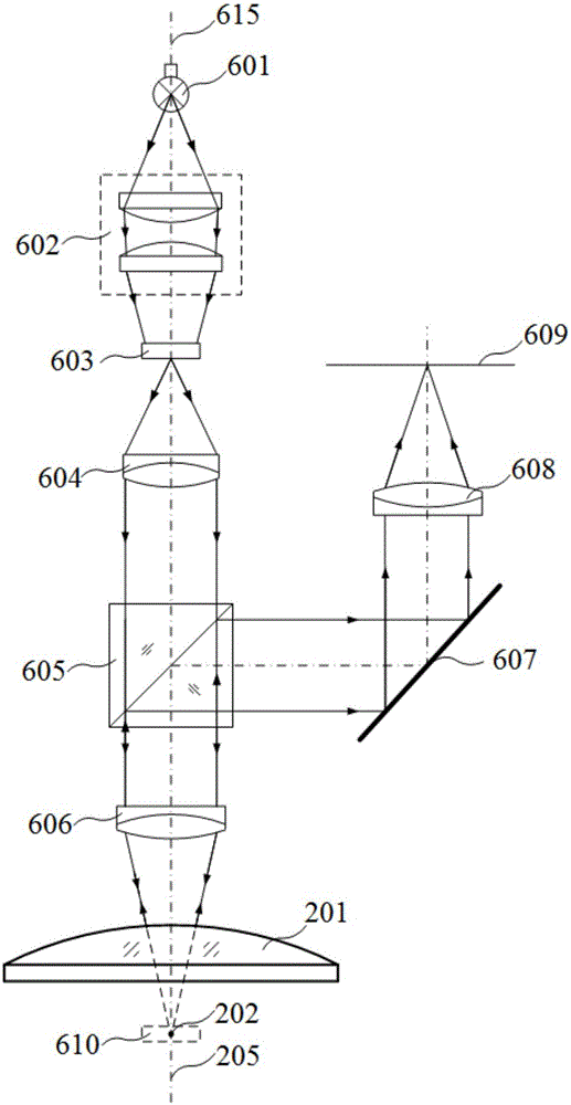
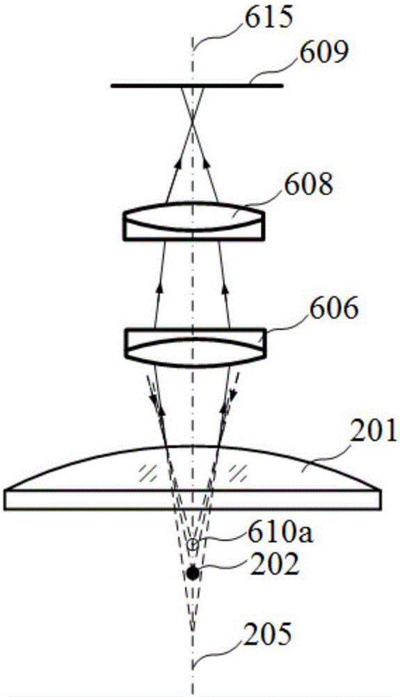
[0030] The spherical centering unit provides a hardware basis for centering the spherical optical element 201 . figure 1 Shown is a structural diagram of a spherical centering unit. The spherical surface centering unit includes a light source, a light source focusing lens group, a reticle, a collimating lens, a beam splitter, an objective lens, a mirror, an imaging mirror and a CCD; the light emitted by the light source 601 in the spherical surface centering unit passes through the light source focusing lens group 602 is irradiated on the reticle 603, and the reticle 603 is engraved with crosshairs. Then the light enters the beam splitter 605 after being transmitted through the collimator lens 604, and after being transmitted through the beam splitter 605, it is irradiated on the spherical optical element 201 through the objective lens 606 and reflected on its surface. At this time, the cross on the reticle 603 The image formed by the wire is the reticle image 610 . The refl...


PUM


Abstract

The invention discloses a spherical surface automatic centering method applied to spherical surface optical element surface defect detection. The method comprises the following steps that a spherical surface centering unit is initialized, and then a spherical surface optical element is moved to an initial position; Z-direction scanning is performed, and the clearest crosshair image is found by utilizing an image entropy definition evaluation function in the scanning process; then whether the crosshair is a surface image or a spherical center image is judged; if the crosshair is the surface image, the spherical center image is found through scanning along Z-direction, and radius of curvature of the spherical surface optical element is measured; if the crosshair is the spherical center image, the optical axis of the spherical surface optical element is enabled to be overlapped with the optical axis of the spherical surface centering unit through movement; and finally fitting is performed on the center of the crosshair image by a least square method optimal circle fitting method to obtain movement tracks, calculation of the maximum deviation of the crosshair image is completed, and the maximum deviation is judged so that shafting consistency adjustment is completed. Automatic centering of the spherical surface optical element is realized so that centering efficiency and centering precision are greatly enhanced.

Description

technical field [0001] The invention belongs to the technical field of machine vision detection, and in particular relates to an automatic spherical surface centering method applied to surface defect detection of spherical optical elements. Background technique [0002] Spherical optical elements are widely used in large-aperture space telescopes, inertial confinement fusion (ICF) systems, and high-energy laser systems. Unnecessary scattering and diffraction will also occur in the system, which will cause energy loss and may cause secondary damage. Therefore, a system and method for evaluating surface defects of spherical optical components is designed to realize automatic and accurate quantitative evaluation of surface defects of spherical optical components. . [0003] Based on the designed spherical optical element performance defect evaluation system and method, the present invention proposes an automatic centering method applied to the detection of spherical optical el...

Claims


Application Information

Patent Timeline
Patent Type & Authority Applications(China)
IPC IPC(8): G01B11/255
Inventor 杨甬英刘东张毅晖李阳柴惠婷吴凡曹频谢世斌熊浩亮
Owner ZHEJIANG UNIV
Why Eureka
Try Eureka