Small-current grounding line selection device line-outgoing system

A technology of low-current grounding and line selection device, applied in the direction of fault location, etc., can solve the problems of different line fault troubleshooting errors, affecting the lower line troubleshooting, etc.

Inactive Publication Date: 2015-12-16
HEFEI HAICHANG ELECTRICAL TECH
5 Cites 5 Cited by

AI-Extracted Technical Summary

Problems solved by technology

[0003] Since the layout of the power grid is greatly affected by factors such as terrain, often different terrains, after the grounding line is...

Abstract

A small-current grounding line selection device line-outgoing system is connected with a voltage transformer, a grounding loop and a grounding line selection device, and comprises a zero sequence current transformer input terminal, CT ends and zero sequence transformers, which are connected in sequence. The grounding line selection device is connected with a zero sequence current transformer, the voltage transformer and a contactor; by adding the CT ends and the zero sequence transformers or secondary line accessing devices to the current transformer input terminal, use needs of full cable outgoing, overhead line outgoing or mixed line outgoing are met; and when the voltage transformer detects a zero sequence voltage, the grounding loop is controlled to be connected, and then, fault lines are judged according to the current data collected by the zero sequence current transformer. The small-current grounding line selection device line-outgoing system, for line outgoing modes of different landforms, eliminates errors, realizes line fault elimination accurately and quickly, and guarantees normal work of the grounding line selection device.

Application Domain

Fault location

Technology Topic

ContactorEngineering +5

Image

  • Small-current grounding line selection device line-outgoing system
  • Small-current grounding line selection device line-outgoing system
  • Small-current grounding line selection device line-outgoing system

Examples

  • Experimental program(1)

Example Embodiment

[0015] The content of the present invention will be described below in conjunction with specific embodiments.
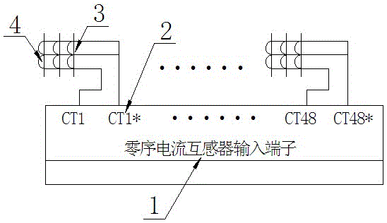
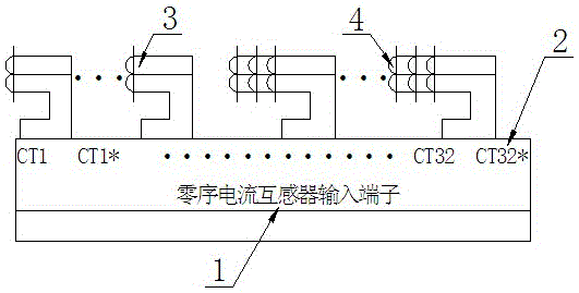
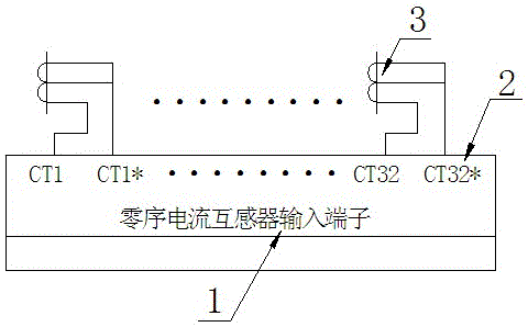
[0016] Such as figure 1 , figure 2 with image 3 As shown, the outlet system of the small current grounding line selection device is connected with a voltage transformer, a ground loop, and a grounding line selection device, and includes a zero sequence current transformer input terminal 1, a CT terminal 2 and a zero sequence transformer 3 connected in sequence, The grounding line selection device is connected to the zero-sequence current transformer, voltage transformer and contactor respectively, and CT terminal 2, zero-sequence transformer 3 or secondary line access device 4 is installed on the input terminal of the current transformer to meet the requirements of all cables For the use requirements of outgoing, overhead outgoing or mixed outgoing methods, when the voltage transformer detects the zero-sequence voltage, the ground loop is controlled to conduct, and then the faulty line is judged according to the current data collected by the zero-sequence current transformer. According to different terrain routing methods, errors are eliminated, line faults can be eliminated accurately and quickly, and the normal operation of the grounding line selection device is guaranteed.
[0017] The electrical characteristics of the zero-sequence CT terminal 2 of the same site should be basically the same. The polarity of all zero-sequence CT terminals 2 must be strictly consistent. Pay special attention to the site where the zero-sequence CT terminal 2 and the three-phase CT terminal 2 are mixed. For more than two stages For the busbar system, it is necessary to ensure that the polarity of the CT terminal 2 of all the lead-in devices is the same. At the same time, pay attention to the direction of the zero sequence voltage and the direction of the zero sequence current to ensure the normal state. The zero-sequence transformer 3 is generally installed under the cable head. The grounding wire of the cable sheath above the zero-sequence transformer 3 must pass through the CT terminal 2 and ground on the line side; the cable sheath below the zero-sequence transformer 3 cannot pass through the zero Sequence transformer 3 to avoid forming a short circuit loop.
[0018] Such as figure 1 The shown full-cable outlet method is to install a zero-sequence transformer 3 and a secondary line access device 4 on each outlet line, and the polarity of the CT terminal 2 remains the same.
[0019] Such as figure 2 The overhead outgoing system shown usually only has CT terminal 2 of phase A and C, and phase B must be equipped with CT terminal 2, which is consistent with the accuracy and changeability of CT terminal 2 of phase A and C, and is connected to zero sequence The filter is introduced into the device.
[0020] Such as image 3 The shown outgoing hybrid system includes overhead outgoing and cable outgoing systems. The zero sequence current generated by the three-phase CT terminal 2 zero sequence filter method is the same as the zero sequence current generated by the zero sequence current transformer. The difference in the transformation ratio does not affect the device judgment.
[0021] The above are only the preferred embodiments of the present invention and are not intended to limit the present invention. Any modification, equivalent replacement and improvement made within the spirit and principle of the present invention shall be included in the protection of the present invention. Within range.

PUM

no PUM

Description & Claims & Application Information

We can also present the details of the Description, Claims and Application information to help users get a comprehensive understanding of the technical details of the patent, such as background art, summary of invention, brief description of drawings, description of embodiments, and other original content. On the other hand, users can also determine the specific scope of protection of the technology through the list of claims; as well as understand the changes in the life cycle of the technology with the presentation of the patent timeline. Login to view more.
Why Eureka
Try Eureka