Internal-focusing high power focusing lens

A focusing lens and high-power technology, applied in the field of focusing lenses, can solve the problems of difficulty in multi-beam high-energy lasers, inability to achieve precise focusing, and the inability of large-diameter focusing lenses to move accurately, achieving the effect of simple and compact structure, convenient and fast focusing

Active Publication Date: 2015-12-16
HARBIN INST OF TECH
View PDF4 Cites 6 Cited by
  • Summary
  • Abstract
  • Description
  • Claims
  • Application Information

AI Technical Summary

Problems solved by technology

[0003] The present invention aims to solve the problem that the large-diameter focusing lens of the existing high-power laser cannot be moved accurately, cannot achieve precise focusing, and it is difficult to focus multiple beams of high-energy lasers into a small section of space, and further provides an adjustable focus. power focus lens

Method used


Image

  • Internal-focusing high power focusing lens
  • Internal-focusing high power focusing lens
  • Internal-focusing high power focusing lens

Examples


specific Embodiment approach 1

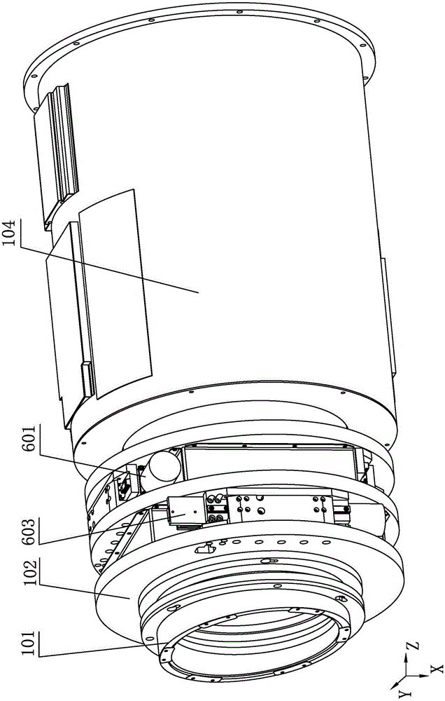
[0008] Specific implementation mode one: combine Figure 1-Figure 10 Explain that a focusable high-power focusing lens of this embodiment includes a lens shield assembly 101, a lens replacement unit assembly 102, an X-direction position adjustment assembly 603, a Y-direction position adjustment assembly 601, and a Z-direction position adjustment assembly 104;

[0009] The lens shield assembly 101 is installed on the lens replacement unit assembly 102, and the lens replacement unit assembly 102 is installed on the X-direction position adjustment assembly 603, and the X-direction position adjustment assembly 603 is used to drive the lens driving assembly 102 to move in the X direction, The X-direction position adjustment assembly 603 is installed on the Y-direction position adjustment assembly 601, the Y-direction position adjustment assembly 601 is used to drive the X-direction position adjustment assembly 603 to move in the Y direction, and the Y-direction position adjustment ...

specific Embodiment approach 2

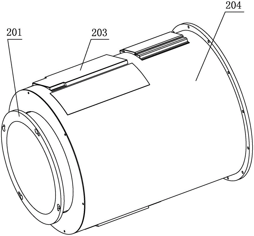
[0010] Specific implementation mode two: combination Figure 2-Figure 3 Explain that the Z-direction position adjustment assembly 104 of this embodiment includes a lens focusing lens barrel 201, a lens housing 204, and a drive assembly 403; the drive assembly 403 includes a motor 504, a motor base 503, a Z-direction screw pair, and a support plate 501;

[0011] The lens housing 204 is a cylindrical housing, the lens focusing lens barrel 201 and the driving assembly 403 are arranged in the lens housing 204, the motor 504 is installed on the motor base 503, and the motor base 503 is installed on the lens housing 204 to support The plate 501 is installed on the lens housing 204, the lead screw 506 of the Z direction lead screw pair is installed on the support plate 501 through the bearing seat 505, the output end of the motor 503 is connected with the lead screw 506 of the Z direction lead screw pair, and the Z direction lead screw The auxiliary screw nut 507 is connected with th...

specific Embodiment approach 3

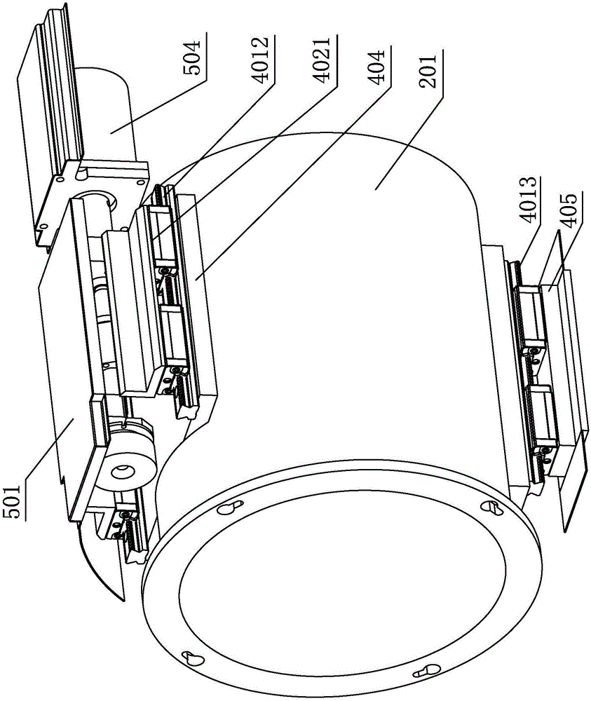
[0012] Specific implementation mode three: combination Figure 4 Note that the drive assembly 403 of this embodiment also includes a lower linear guide rail 4013, an upper guide rail base 404, a lower guide rail base 405, a lower slider base 4023, two upper linear guide rails 4012 and two upper slider bases 4021 ;

[0013] The lower slider base 4023 is installed on the lower part of the lens focusing lens barrel 201, the lower linear guide rail 4013 is installed on the lower part of the lower slider base 4023, the lower guide rail base 405 is installed on the lens housing 204, and the lower linear guide rail 4013 is slidably arranged On the lower guide rail base 405; the upper guide rail base 404 is installed on the top of the lens focusing lens barrel 201, and two upper linear guide rails 4012 are installed side by side along the axial direction of the lens focusing lens barrel 201 on the upper guide rail base 404. The upper slider bases 4021 are respectively connected with ...


PUM


Abstract

The invention provides an internal-focusing high power focusing lens, relates to the focusing lens and aims to solve the problems that an existing high-power laser large-aperture focusing lens fails to move precisely, precise focusing is unavailable, and multiple beams of high-energy lasers are difficult to focus to a minimal cross section in space. The internal-focusing high power focusing lens comprises a lens shielding sheet assembly, a lens replacing unit assembly, an X-direction position adjusting assembly, a Y-direction position adjusting assembly and a Z-direction position adjusting assembly. The lens shielding sheet assembly is installed on the lens replacing unit assembly. The lens replacing unit assembly is installed on the X-direction position adjusting assembly. The X-direction position adjusting assembly is used for driving a lens driving assembly to move in the X direction. The X-direction position adjusting assembly is installed on the Y-direction position adjusting assembly. The Y-direction position adjusting assembly is used for driving the X-direction position adjusting assembly to move in the Y direction. The Y-direction position adjusting assembly is installed on the Z-direction position adjusting assembly. The internal-focusing high power focusing lens is suitable for focusing the focusing lens.

Description

technical field [0001] The invention relates to a focusing lens and belongs to the field of optical lens adjustment devices. Background technique [0002] Focusing lens engineering is widely used, such as various laser processing, laser inspection, etc. Most of the equipment can also achieve focusing or even automatic focusing. However, the large-aperture focusing lenses currently used for high-power (million-joule) lasers cannot achieve precise focusing in the three directions of the X-axis, Y-axis, and Z-axis. difficulty. Contents of the invention [0003] The present invention aims to solve the problems that the large-diameter focusing lens of the existing high-power laser cannot be moved accurately, cannot achieve precise focusing and the difficulty exists in focusing multiple high-energy laser beams into a small section of space, and further provides an adjustable focus high Power focus lens. [0004] The technical solution adopted by the present invention to solve...

Claims


Application Information

Patent Timeline
Patent Type & Authority Applications(China)
IPC IPC(8): G02B7/02G02B7/04
CPCG02B7/023G02B7/04
Inventor 张鹏于福利白清顺刘保麟卢礼华
Owner HARBIN INST OF TECH
Why Eureka
Try Eureka