
Magnetostatic field magnetizing device and method at normal temperature

A magnetizing device, a technology of static magnetic field, applied in the direction of magnetic objects, transportation and packaging, conveyor objects, etc., can solve the problems of unsuitable long-term, frequent use, large area of ​​magnetization equipment, and high instantaneous current, so as to improve the charging efficiency. Magnetic efficiency, reduce production energy costs, and save energy

Active Publication Date: 2015-12-16
天津博雅全鑫磁电科技有限公司
View PDF11 Cites 7 Cited by
  • Summary
  • Abstract
  • Description
  • Claims
  • Application Information

AI Technical Summary

Problems solved by technology

This type of equipment mainly has the following disadvantages: 1. The traditional magnetization equipment has large energy consumption and low efficiency; 2. The traditional magnetization equipment mainly uses pulse magnetization, the control system is simple, there is no protection device, and most of them are manually controlled. ; 3. The traditional magnetizing equipment uses hollow coils. The high current passing through the magnetizing process will generate high heat, which is not suitable for long-term and frequent use. If cooling equipment is added, more energy consumption will be increased; 4. Traditional magnetizing equipment Occupying a large area and high instantaneous current present potential safety hazards
[0004] Patent No. 201310535597.5 discloses a static magnetic field magnetization device and magnetization method. Its disadvantages are high temperature magnetization, high energy consumption, long magnetization time and low efficiency, which affects its promotion.

Method used


Image

  • Magnetostatic field magnetizing device and method at normal temperature
  • Magnetostatic field magnetizing device and method at normal temperature
  • Magnetostatic field magnetizing device and method at normal temperature

Examples


Embodiment 1

[0045] The sample is a sintered Nd-Fe-B magnet with commercial grade N50H. The magnet performance is: Br=14.0KGs; Hcb=12.9kOe; Hcj=16kOe; Hk / Hcj=0.7; (BH)m=48MGOe; commercial grade is N42UH The sintered Nd-Fe-B magnet, the magnet properties are: Br=13.0KGs; Hcb=12kOe; Hcj=25kOe; Hk / Hcj=0.6; (BH)m=40MGOe. The dimensions of the magnets of the above two brands are both cuboids of 45×11.5×2 mm, and the orientation direction of the magnets is the direction of 2 mm.

[0046] In the experiment, the above two different brands of NdFeB permanent magnets were magnetized in a static magnetic field, and the magnets were sent into the material guide channel of the magnetization part by the automatic feeding part, so that the magnets corresponded to the positions of the magnetization heads, and the magnetization The direction is consistent with the direction of the magnetic field, and they stay for 5 seconds and 10 seconds respectively. The results are shown in Table 1. As can be seen from...

Embodiment 2

[0048] The sample adopts a ferrite magnet whose commercial grade is Y35, and the magnet properties are: Br=4.1KGs; Hcb=2.35kOe; Hcj=2.5kOe. The size of the magnet is a cuboid of 44.5×15×3mm, and the orientation direction of the magnet is the direction of 3mm.

[0049] Send the magnet into the material guide channel of the magnetization part, make the magnet correspond to the position of the magnetization head, the magnetization direction is consistent with the magnetic field direction, and stay for 8 seconds. The results are shown in Table 1. It can be seen from Table 1 that the magnetic flux of the ferrite magnet after magnetization is consistent with the pulse magnetization flux at normal temperature, indicating that the present invention can saturate and magnetize the ferrite magnet in a static magnetic field under normal temperature.

[0050] Magnetic flux comparison after the magnetization of the pulse magnetizer and the magnetization of the present invention after the ta...


PUM

PropertyMeasurementUnit
radiusaaaaaaaaaa
heightaaaaaaaaaa

Abstract

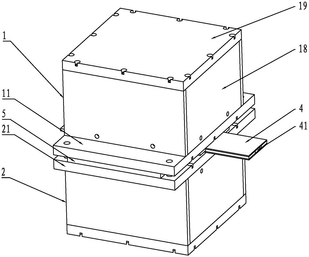
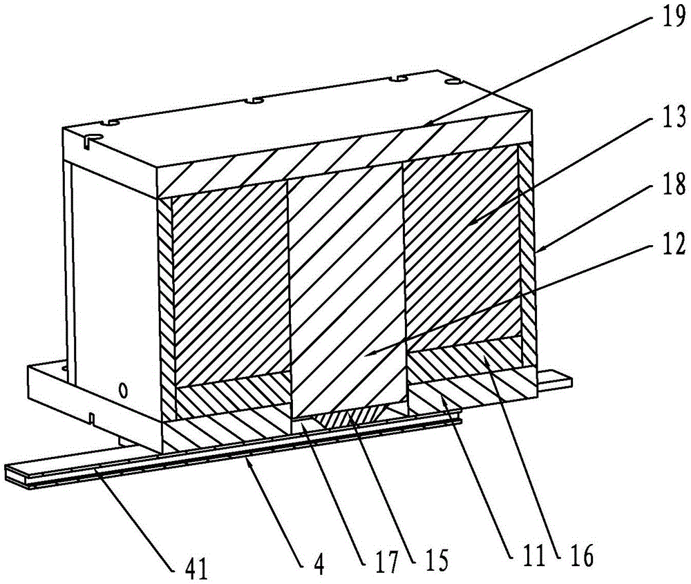
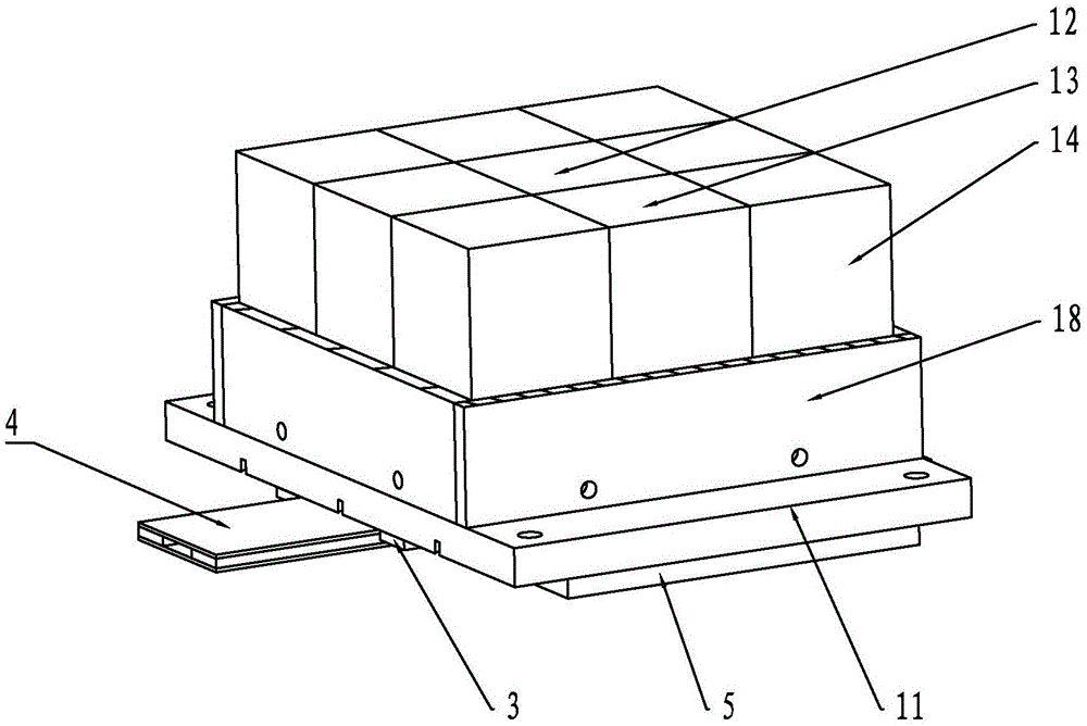
The invention belongs to the technical field of magnetizing, and aims to provide a magnetostatic field magnetizing device and method at a normal temperature. The device is compact in structure, stable in performance, safe and reliable, capable of saving energy and high in magnetizing efficiency. The device comprises an upper magnetizing source device and a lower magnetizing source device. The upper magnetizing source device comprises an upper supporting plate, yoke iron bodies and magnetizing magnetic steel bodies. Each yoke iron body is in the shape of a cuboid, and the four side faces of each yoke iron body are each provided with one magnetizing magnetic steel body in a pasting mode. The lower ends of the yoke iron bodies protrude out of the magnetizing magnetic steel bodies, and magnetizing heads are pasted in the central positions of the yoke iron bodies. The bottoms of the magnetizing magnetic steel bodies are fixedly attached to the upper supporting plate. A through groove is formed in the central position of the upper supporting plate, and the magnetizing heads of the yoke iron bodies are located in the through groove of the upper supporting plate. The structure of the lower magnetizing source device is the same as the structure of the upper magnetizing source device, and the lower magnetizing source device and the upper magnetizing source device are symmetrically arranged. A material guide plate is arranged between a lower supporting plate of the lower magnetizing source device and the upper supporting plate of the upper magnetizing source device, material guide through grooves are formed in the material guide plate, and the positions of the material guide through grooves correspond to those of the magnetizing heads. The lower supporting plate is fixedly connected with the upper supporting plate.

Description

technical field [0001] The invention belongs to the field of magnetization technology, in particular to a static magnetic field magnetization device and a magnetization method at normal temperature. Background technique [0002] With the development of permanent magnet materials, magnetic materials cover a large number of electronic and electrical products, and are one of the foundation and backbone industrial sectors of the material industry. With the rapid rise of my country's electronics and electrical industries, my country has become the world's largest producer and consumer of magnetic materials. Many high-tech magnetic materials and components will also be mainly produced and purchased by Chinese companies. The annual market sales of permanent magnet materials have already More than $10 billion. Magnetic materials will also become one of the pillar industries in my country's national economy. [0003] The magnetizing process is an essential process for NdFeB permanen...

Claims


Application Information

Patent Timeline
Patent Type & Authority Applications(China)
IPC IPC(8): H01F13/00B65G47/82
Inventor 王发立张铁军王德文游峰
Owner 天津博雅全鑫磁电科技有限公司
Learn More