
Combined antenna system and mobile terminal

A technology for combining antennas and mobile terminals, which is applied in antennas, antenna supports/mounting devices, antenna unit combinations with different polarization directions, etc., can solve problems such as lowering product quality, reducing product radiation efficiency, and fragile shrapnel, and achieves Feed loss is small, the effect of solving large-area coexistence and high radiation efficiency

Active Publication Date: 2015-12-16
YULONG COMPUTER TELECOMM SCI (SHENZHEN) CO LTD
View PDF10 Cites 14 Cited by
  • Summary
  • Abstract
  • Description
  • Claims
  • Application Information

AI Technical Summary

Problems solved by technology

[0002] In the mobile terminal equipment industry such as mobile phones and tablet PCs, with the continuous improvement of user experience requirements for the appearance and feel of products, metal decorative mobile products with good touch and excellent wear resistance have become the mainstream of consumption in this industry However, since the unique shielding performance of the metal back shell and metal frame will seriously reduce the reliability of the antenna, therefore, while conforming to the product development trend, the major manufacturers put forward higher requirements on the design of the antenna. Require
[0003] In order to solve this technical problem, in the prior art, a non-metallic area is usually arranged on a large area on the metal back cover to reduce its interference to the signal, but this structure also reduces the quality of the product accordingly, which is not conducive to product promotion; the prior art In another solution, the shrapnel is set on the inner side of the antenna system, and it is matched with the metal back cover by direct feeding to realize the coexistence of it and the metal in a large area, but this structure has disadvantages such as the shrapnel is fragile, The reliability of the antenna is reduced, and because the structure is not easy to adjust the resonant frequency of the antenna, the radiation efficiency of the product is greatly reduced

Method used

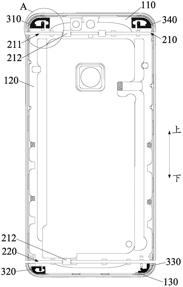
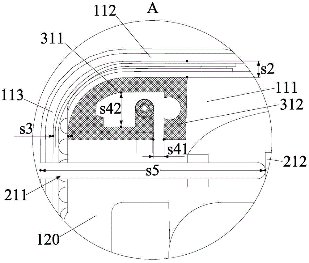
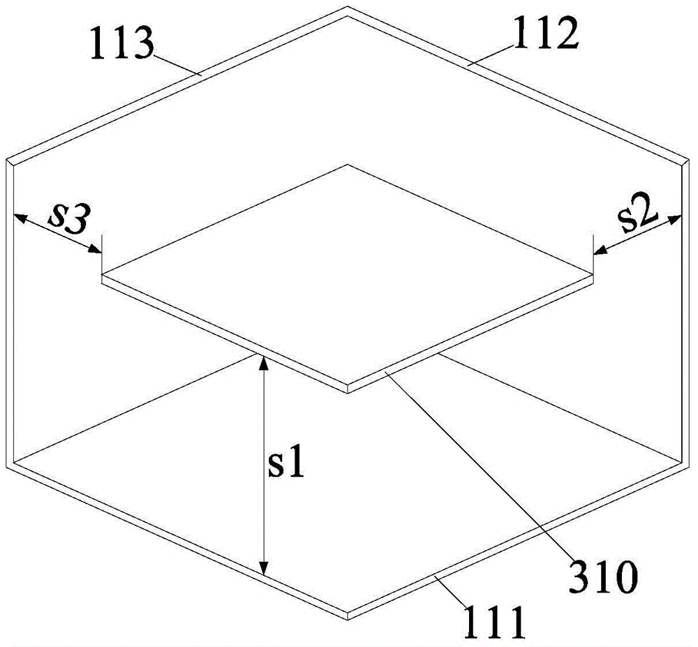

Image

  • Combined antenna system and mobile terminal
  • Combined antenna system and mobile terminal
  • Combined antenna system and mobile terminal

Examples


Embodiment Construction

[0031] In order to understand the above-mentioned purpose, features and advantages of the present invention more clearly, the present invention will be further described in detail below in conjunction with the accompanying drawings and specific embodiments. It should be noted that, in the case of no conflict, the embodiments of the present application and the features in the embodiments can be combined with each other.

[0032] In the following description, many specific details are set forth in order to fully understand the present invention. However, the present invention can also be implemented in other ways different from those described here. Therefore, the protection scope of the present invention is not limited by the specific details disclosed below. EXAMPLE LIMITATIONS.

[0033] Refer below Figure 1 to Figure 3 The combined antenna system according to some embodiments of the invention is described.

[0034] Such as Figures 1 to 3 As shown, the embodiment of the f...


PUM

PropertyMeasurementUnit
Lengthaaaaaaaaaa

Abstract

The invention provides a combined antenna system and a mobile terminal, and the combined antenna system is used in cooperation with a metal back shell of the mobile terminal. The metal back shell comprises a base plate, a side plate and an end plate, wherein the side plate and the end plate are connected to the base plate. The combined antenna system comprises two stereo coupling antennas, each stereo coupling antenna comprises a first metal line which can generate low frequency resonance and a second metal line which can generate high frequency resonance, the stereo coupling antennas are connected with an RF feed source of the mobile terminal, and placed at included angles formed by the base plate, the side plate and the end plate, first, second and third gaps are formed among the base plate, the side plate and the end plate, and thus, simultaneous coupling feed of the stereo coupling antennas with the base plate, the side plate and the end plate is realized. The combined antenna system provided by the invention is suitable for the metal back shell, tuning in different frequency ranges is flexible and convenient via structure design, radiation loss of products is reduced, and requirements of different network standards for the mobile terminal in future can be met.

Description

technical field [0001] The present invention relates to the technical field of wireless communication, in particular to a combined antenna system and a mobile terminal with the combined antenna system. Background technique [0002] In the mobile terminal equipment industry such as mobile phones and tablet PCs, with the continuous improvement of user experience requirements for the appearance and feel of products, metal decorative mobile products with good touch and excellent wear resistance have become the mainstream of consumption in this industry However, since the unique shielding performance of the metal back shell and metal frame and other decorations will seriously reduce the reliability of the antenna, therefore, while conforming to the product development trend, higher requirements are put forward for major manufacturers in the design of the antenna. Require. [0003] In order to solve this technical problem, in the prior art, a non-metallic area is usually arranged...

Claims


Application Information

Patent Timeline
IPC IPC(8): H01Q1/22H01Q21/24H01Q5/20H04M1/20
CPCH01Q1/22
Inventor 姚德才杨攀
Owner YULONG COMPUTER TELECOMM SCI (SHENZHEN) CO LTD
Learn More