

Vessels with Bottom Air Chambers
A technology of ships and air chambers, which is applied in the direction of ship construction, hull, bilge keel, etc. It can solve the problems of air chambers that cannot prevent cracking and do not ensure the integration of wave contours, and achieve the effect of preventing flow separation
- Summary
- Abstract
- Description
- Claims
- Application Information
AI Technical Summary
Problems solved by technology
Method used
Image

Examples
Embodiment Construction
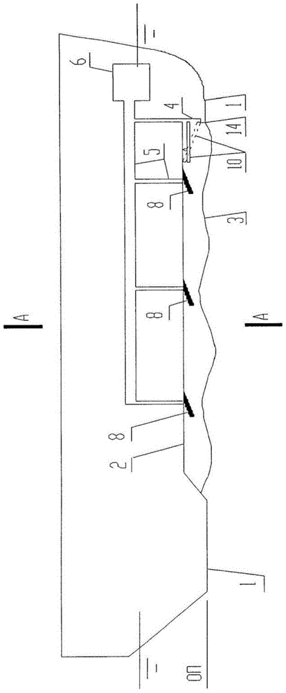
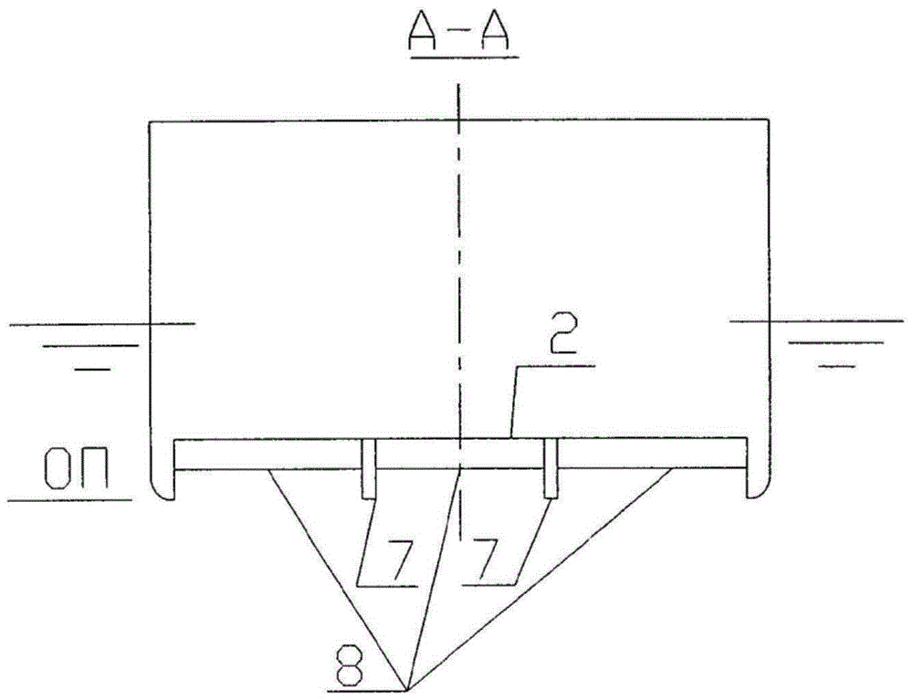
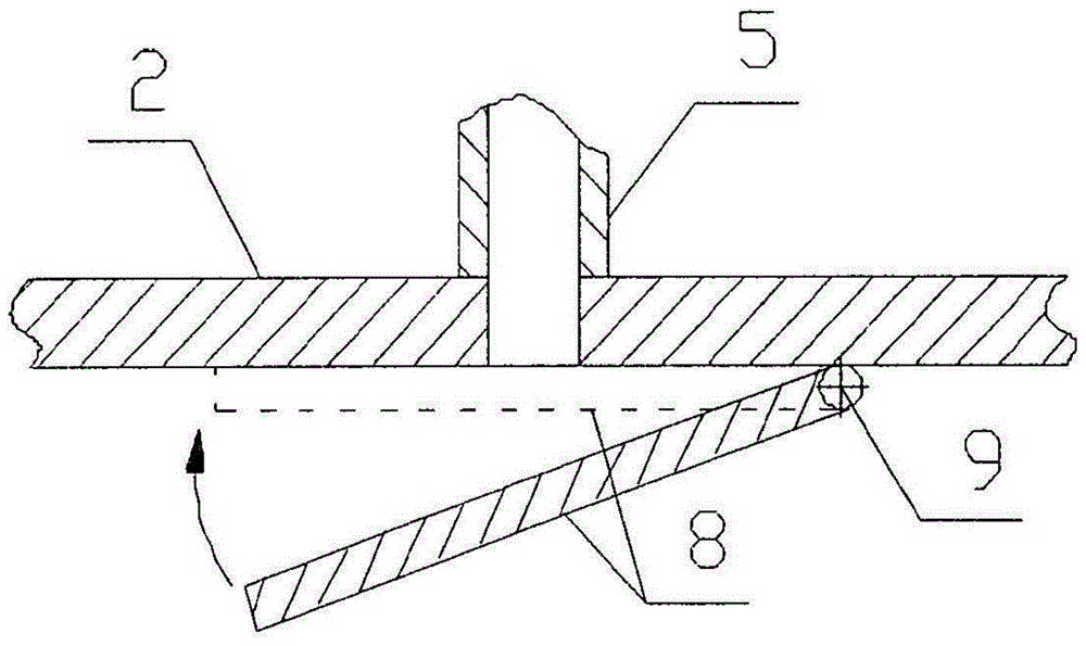
[0032] The proposed vessel with an air layer on the bottom 1 ( figure 1 ) has: a groove 2 for forming an air layer, i.e. an integral cavity 3 with a wave profile made in the vessel bottom 1 (which starts at a step 4); and an air source 6, This air source 6 is spatially connected to the groove 2 via a line 5 for conveying air to the cavity in order to create an air layer under the bottom 1 . Inside the groove 2 there is a longitudinal keel 7 placed parallel to the center line and intended to restrain the lateral movement of the air on the bottom of the groove 2 ( figure 2 ); and the transverse baffles 8, which are arranged successively along the flow direction of the groove 2. The above-mentioned transverse baffle 8 ( image 3 ) are mounted in such a way that they can be deployed into the working position and loaded back into the bottom of the groove 2 by means of their pivoting about the mandrel 9 transverse to the center line of the vessel and adjacent to the transverse ba...
PUM
 Abstract
Description
Claims
Application Information