Eureka AIR delivers breakthrough ideas for toughest innovation challenges, trusted by R&D personnel around the world.

Metal wire and zipper using same

A metal wire and zipper technology, applied in the field of zippers, can solve problems such as difficult to prevent theft and poor safety, and achieve the effect of preventing sliding, high safety and maintaining flexibility

Active Publication Date: 2015-12-23
DET IND DESIGN
View PDF17 Cites 50 Cited by
  • Summary
  • Abstract
  • Description
  • Claims
  • Application Information

AI Technical Summary

Problems solved by technology

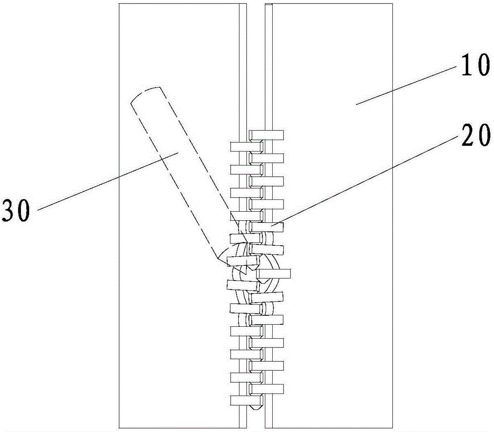
[0003] like figure 1 As shown, the existing metal zipper generally includes a webbing 10 and chain elements 20 arranged and engaged on the webbing 10. In order to ensure that the chain elements 20 on the two webbings 10 can engage with each other, two adjacent chains on the same webbing 10 There is generally a certain distance between the teeth 20, which needs to be greater than the thickness of the fastener elements 20 to ensure that the fastener elements on the two ribbons 10 can be arranged alternately, that is, between two adjacent fastener elements 20 on the same ribbon 10. If there is a sharp object 30 (such as a pen tip, scissors, etc.) piercing into the space, the webbing section at the corresponding position can be lifted to make it bend and deform, so that the chain teeth that have already been engaged with each other at the webbing section position 20 separate from each other, and then open the zipper, the safety is relatively poor, and it is difficult to play the role of anti-theft

Method used


Image

  • Metal wire and zipper using same
  • Metal wire and zipper using same
  • Metal wire and zipper using same

Examples


Embodiment Construction

[0037] The present invention will be further described below in conjunction with the accompanying drawings and specific embodiments.

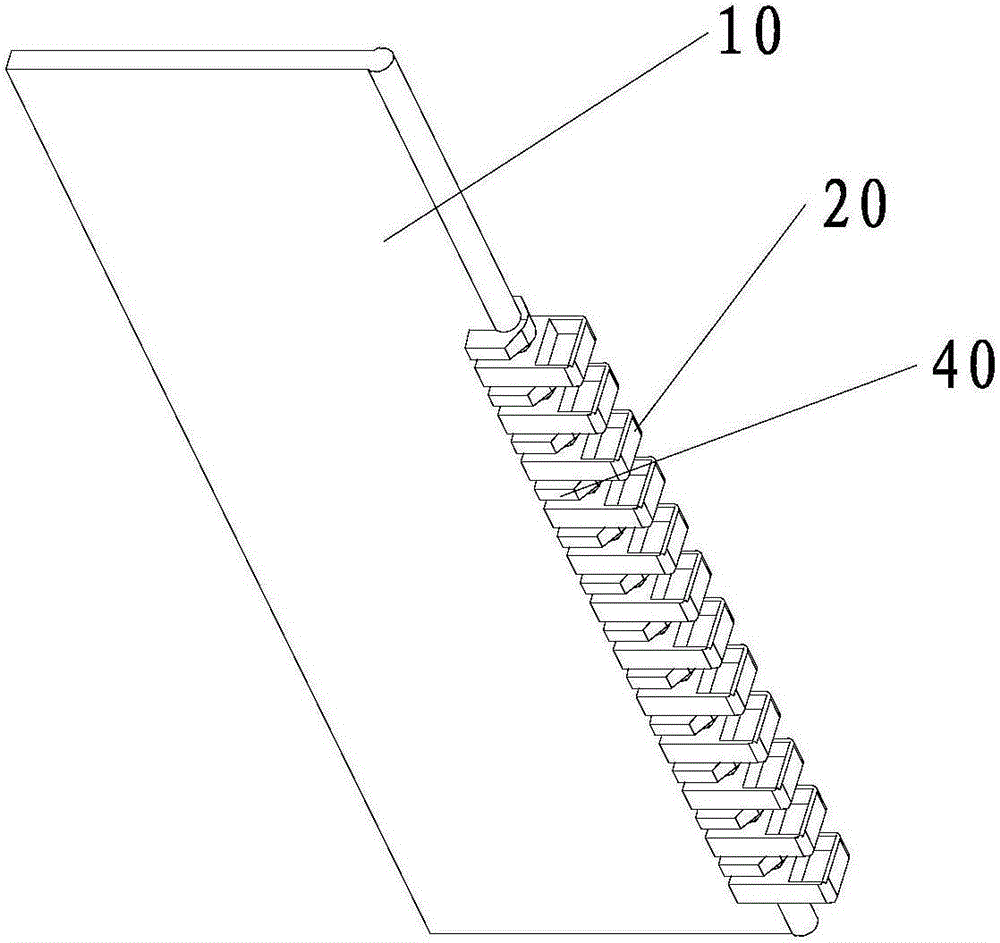
[0038] Such as figure 2 As shown, the zipper provided in this embodiment includes a webbing 10 and fastener elements 20 arranged and engaged on the webbing 10. The fastener elements 20 are metal fastener elements. The structure of the webbing 10 and the fastener elements 20 is a conventional structure. The fastener elements 20 The arrangement pitch on the webbing 10 is also the same as the existing fastener element pitch. It should be noted that zippers are generally used in pairs, that is, each zipper has two webbings 10 engaged with fastener elements 20. Since the structures of the two webbings are the same, for the sake of clarity in the view, the figure 2 Only one webbing 10 is shown in .

[0039] In this embodiment, on the basis of a conventional zipper, auxiliary teeth 40 are arranged between every two fastener elements 20 on the same...


PUM


Abstract

The invention provides a metal wire and a zipper using the same. The metal wire is in a shape of a straight line, and comprises a head part and two leg parts which are connected with the head part and arranged symmetrically, wherein the ends, not connected with the head part, of the two leg parts stretch in opposite directions, a U-shaped groove is formed between the head part and each leg part, mutually symmetric diagonal planes are arranged on two sides, corresponding to the leg parts, of the head part respectively, and the leg parts has sharp corners in the positions of the opening parts of the U-shaped grooves. The zipper comprises a ribbon and zipper teeth arranged on the ribbon in a snap-in manner, and one secondary tooth is arranged between every two chain teeth and is obtained by cutting the metal wire. One secondary tooth is arranged between every two chain teeth, and the distance between two adjacent chain teeth is reduced, so that a sharp object cannot easily pierce the distance or cannot easily take up the ribbon after piercing, the zipper can be prevented from being opened by the sharp object, and the safety is relatively higher.

Description

technical field [0001] The invention relates to a material for making a zipper and a zipper made of the material, in particular to a metal wire and a zipper using the metal wire. Background technique [0002] A zipper is a connector that combines or separates items by means of chain elements arranged in succession. It is widely used in various products such as leather goods and clothing. Common zippers can be divided into nylon zippers, injection molded zippers and metal zippers. Corresponding to nylon zippers and injection molded zippers, metal zippers are often used as anti-theft zippers for bags because they are stronger. [0003] Such as figure 1 As shown, the existing metal zipper generally includes a webbing 10 and chain elements 20 arranged and engaged on the webbing 10. In order to ensure that the chain elements 20 on the two webbings 10 can engage with each other, two adjacent chains on the same webbing 10 There is generally a certain distance between the teeth 20...

Claims


Application Information

Patent Timeline
IPC IPC(8): A44B19/34A44B19/24
Inventor 杨学太骆呈霖唐孝康黄松香
Owner DET IND DESIGN
Why Eureka
Eureka Blog
Learn More