
Automatic welding device of reinforcement cage seam welder

A technology of automatic welding and seam welding machine, applied in the direction of auxiliary equipment, welding equipment, auxiliary welding equipment, etc., can solve the problems affecting the production efficiency and quality of steel cages, irregular solder joints, and high labor intensity of workers. Fast, guaranteed welding quality, time-saving effect

Active Publication Date: 2015-12-23
郑州市聚能建筑机械有限公司
View PDF7 Cites 10 Cited by
  • Summary
  • Abstract
  • Description
  • Claims
  • Application Information

AI Technical Summary

Problems solved by technology

However, most of the traditional steel cages are made by hand, which has high labor intensity, low production efficiency and high cost; or it is made by traditional equipment, which has a low degree of automation, although the production efficiency is higher than that of manual production. However, manual welding is still used for the welding of steel bars and main bars. The quality and speed of welding depend on the welding technology and speed of workers. The irregular shape of solder joints and unstable quality directly affect the production efficiency and quality of steel cages.

Method used


Image

  • Automatic welding device of reinforcement cage seam welder
  • Automatic welding device of reinforcement cage seam welder
  • Automatic welding device of reinforcement cage seam welder

Examples


Embodiment 1

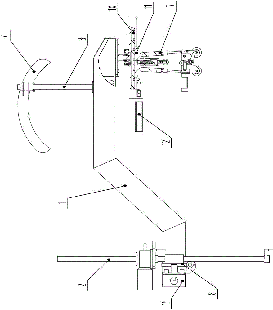
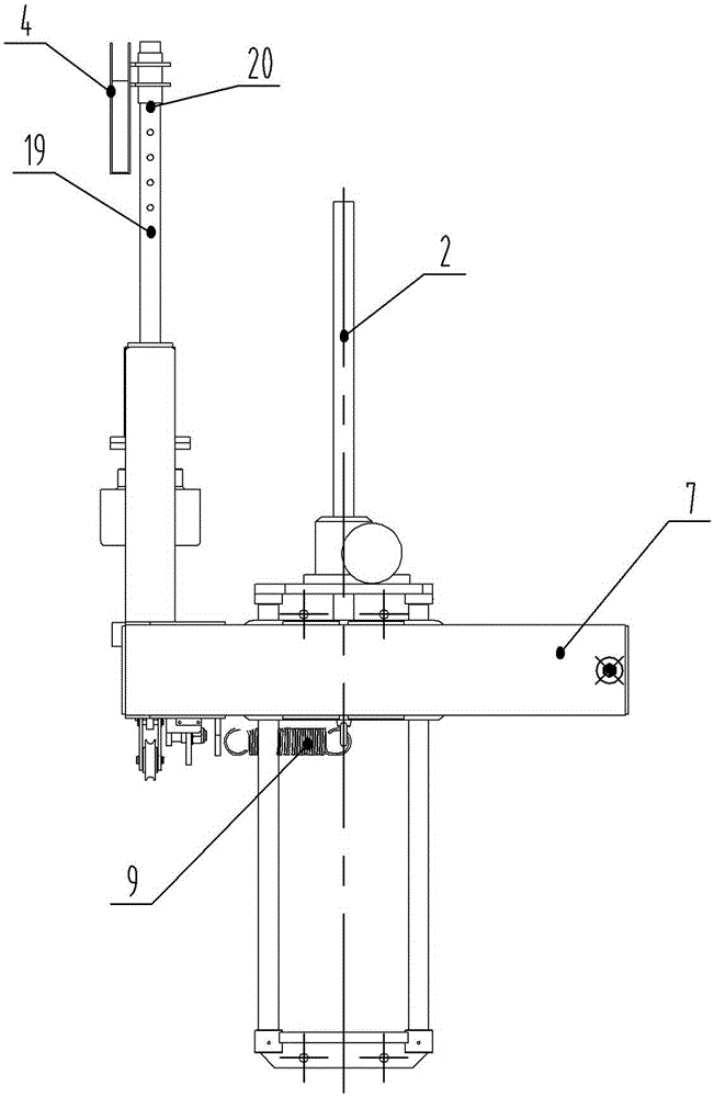
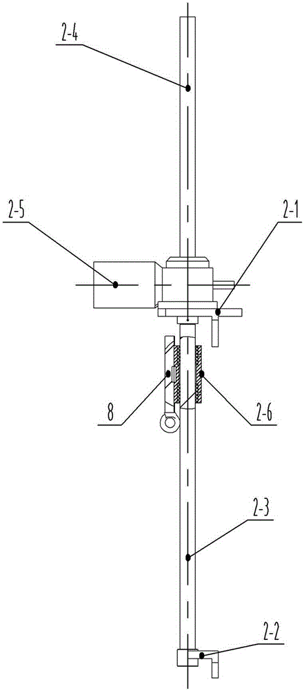
[0029] see Figure 1-2 , 5. In the figure, the automatic welding device of the steel cage roll welding machine of the present invention includes a welding support arm 1 and its lifting mechanism 2, a welding wire support rod 3 and its arc bracket 4, a welding hand mechanism 5 and a welding handle clamping mechanism 6. The welding support arm is a "Z"-shaped structure arranged horizontally, and the lower end of the welding support arm is longitudinally provided with a linear track Ⅰ7 and a slider Ⅰ8 that is slidingly matched with it. The slider Ⅰ is fixedly connected to the lifting mechanism. A tension spring 9 is longitudinally arranged between the block I and the linear track I, and a welding wire support bar and its arc bracket are arranged on the top of the upper end of the welding support arm, and a linear track II10 is provided at the bottom of the upper end of the welding support arm and slides with it. The matched and connected slide block II11 is provided with a cylind...


PUM


Abstract

The invention belongs to the technical field of reinforcement cage seam welding equipment and particularly relates to an automatic welding device of a reinforcement cage seam welder. The automatic welding device comprises a welding support arm, a lifting mechanism of the welding support arm, a welding wire support rod, an arc-shaped bracket of the welding wire support rod, a welding hand mechanism and a welding handle clamping mechanism. The welding support arm is of a horizontal Z shape. A linear rail I and a slide plate connected to the linear rail I in a sliding and matching mode are arranged at the lower end of the welding support arm in the longitudinal direction, and the slide plate is fixedly connected to the lifting mechanism. A tension spring is arranged between a slide block I and the linear rail I in the longitudinal direction. The welding wire support rod and the arc-shaped bracket of the welding wire support rod are arranged on the top of the upper end of the welding support arm. A linear rail II and a slide block II connected to the linear rail II in a sliding and matching mode are arranged on the bottom of the upper end of the welding support arm. An air cylinder I is arranged between the slide block II and the linear rail II, and the slide block II is fixedly connected to the welding hand mechanism. The automatic welding device can replace manual welding to improve the welding efficiency, lower the labor intensity of workers and improve the welding quality.

Description

technical field [0001] The invention belongs to the technical field of steel cage roll welding equipment, in particular to an automatic welding device for a steel cage roll welding machine. Background technique [0002] With the rapid development of domestic road and bridge construction, steel cages are more and more commonly used in pile foundation construction. The production of traditional steel cages is mostly made by hand, which has high labor intensity, low production efficiency and high cost; or it is made by traditional equipment, which has a low degree of automation, although the production efficiency is higher than that of manual production. However, manual welding is still used for the welding of the steel bar and the main bar. The welding quality and speed depend on the worker's welding technology and speed. The irregular shape of the solder joints and the unstable quality directly affect the production efficiency and quality of the steel cage. Contents of the ...

Claims


Application Information

Patent Timeline
IPC IPC(8): B23K37/02B23K37/04B23K37/00B21F31/00
CPCB21F31/00B23K37/00B23K37/0252B23K37/0435
Inventor 梁亮
Owner 郑州市聚能建筑机械有限公司
Learn More