Filters for granulation of paper residues
A papermaking waste residue and filter technology, which is applied in the papermaking field, can solve the problems of increasing labor intensity of workers, frequent screen changing steps, and reducing production efficiency, so as to save removal and installation steps, avoid heat loss and waste, and ensure production efficiency. Effect
- Summary
- Abstract
- Description
- Claims
- Application Information
AI Technical Summary
Problems solved by technology
Method used
Image
Examples
Embodiment 1
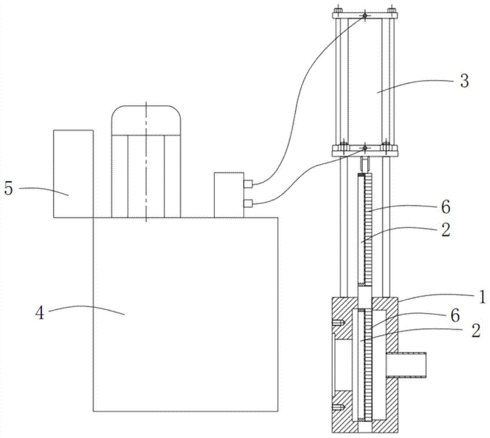
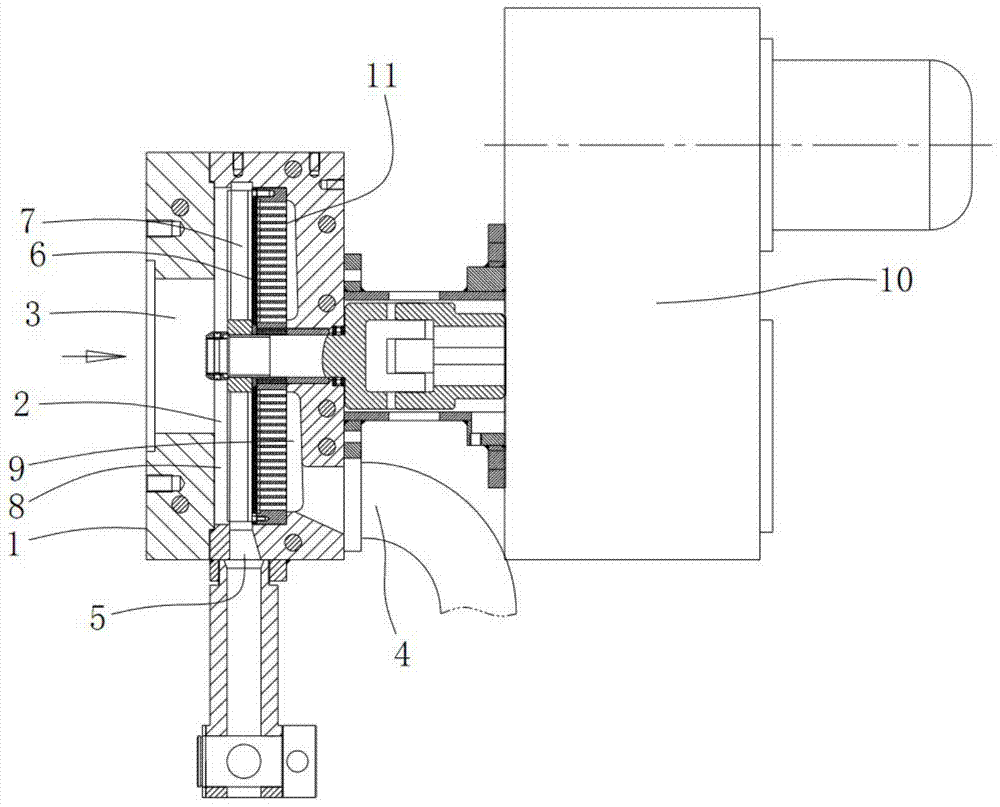
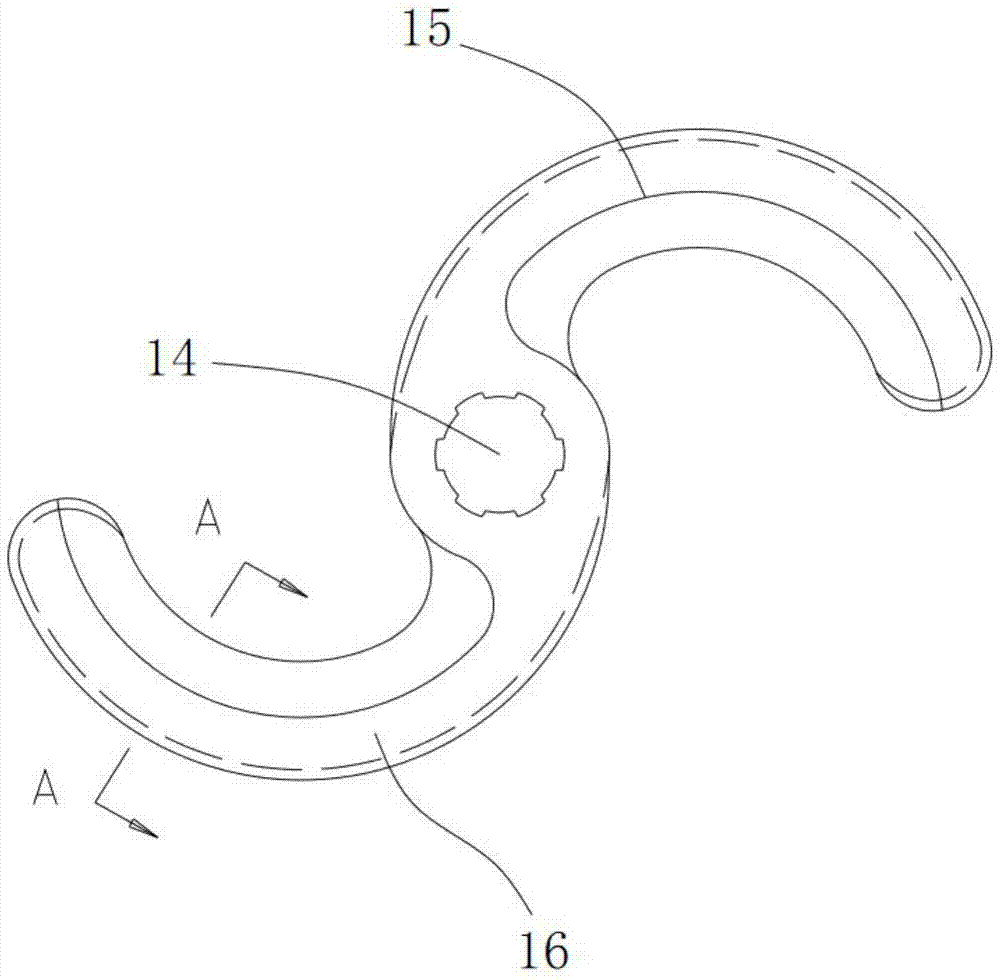
[0048] Example 1, such as figure 2 , 3, 4 show:
[0049] A filter comprising:
[0050] -Case 1, which has a cavity 2, a feed port 3, a discharge port 4 and a slag discharge port 5, and the papermaking waste is plasticized by a granulator to form a plasticized filter to be filtered Fluid, the plasticized fluid to be filtered enters the cavity 2 through the feed port 3, flows out from the discharge port 4 after being filtered, and the impurities in the plasticized fluid are discharged through the slag discharge port 5 ;
[0051] - microporous plate 6, said microporous plate 6 is provided with several through holes at intervals, said microporous plate 6 is arranged in said cavity 2, and said cavity 2 is divided into feeding cavity 8 and outlet Material chamber 9, when the plasticizing fluid passes through the microporous plate 6, the impurities in the plastic fluid are blocked on the side of the microporous plate 6 located at the feeding chamber 8;
[0052] - scraper 7, said...
Embodiment 2
[0055] Example 2, such as figure 2 , as shown in 3 and 4,
[0056] As described in Embodiment 1, a support plate 11 for supporting the microporous plate 6 is also provided in the discharge chamber 9, and the through holes on the microporous plate 6 extend toward the support plate 11, and Through the support plate 11, the side of the microporous plate 6 located in the feed chamber 8 is circular, the edge of the microporous plate 6 matches the side wall of the cavity 2, and the row The slag port 5 is arranged on the side wall of the cavity 2. When the driving device 10 drives the scraper 7, the scraper 7 rotates, and the rotation plane of the scraper 7 is located parallel to the microporous plate 6. On the side of the feeding chamber 8 , the outer edge of the scraper 7 matches the side wall of the feeding chamber 8 , and the slag discharge port 5 is arranged on the side wall below the chamber body 2 .
[0057] The plasticized fluid enters the discharge chamber 9 through the m...
Embodiment 3
[0058] Example 3, such as figure 2 , as shown in 3 and 4,
[0059] As described in Embodiment 1, the scraper 7 includes a knife body 12 and a knife edge 13 arranged on the knife body 12, and the knife edge 13 is located on the side of the microporous plate 6 in the feeding chamber 8 In cooperation, the cutter body 12 includes a mounting seat 14 for connecting with the driving device 10, and a first arc segment 15 and a second arc segment 16 are arranged on the mounting seat 14 apart from each other. The protruding direction of the arc segment 15 and the second arc segment 16 is consistent with the direction of rotation of the cutter body 12, and the blade 13 is made of cemented carbide. When the driving device 10 drives the scraper 7 to rotate, it faces The side of the impurity is the front side, and the side away from the impurity is the rear side. The blade 13 is arranged on the front side of the knife body 12, and the front side and the rear side of the knife body 12 are ...
PUM
 Abstract
Description
Claims
Application Information
 - R&D
- Intellectual Property
- Life Sciences
- Materials
- Tech Scout
- Unparalleled Data Quality
- Higher Quality Content
- 60% Fewer Hallucinations
Browse by: Latest US Patents, China's latest patents, Technical Efficacy Thesaurus, Application Domain, Technology Topic, Popular Technical Reports.
© 2025 PatSnap. All rights reserved.Legal|Privacy policy|Modern Slavery Act Transparency Statement|Sitemap|About US| Contact US: help@patsnap.com


