Zipper discharging device for bag making machine

A technology of a discharging device and a bag making machine, which is applied in the fields of zipper discharging device and zipper discharging device of a bag making machine, and can solve problems such as poor zipper discharging effect, low work efficiency, and affecting enterprise production efficiency and market competitiveness. , to achieve good discharging effect, reduce labor intensity and compact structure

Active Publication Date: 2015-12-23
WUXI KING MO MACHINERY
View PDF13 Cites 1 Cited by
  • Summary
  • Abstract
  • Description
  • Claims
  • Application Information

AI Technical Summary

Problems solved by technology

Although the bag making machines currently on the market can realize the production of zippered packaging bags, the zipper feeding effect is poor, resulting in low work efficiency and affecting the production efficiency and market competitiveness of enterprises.

Method used


Image

  • Zipper discharging device for bag making machine
  • Zipper discharging device for bag making machine

Examples


Embodiment Construction

[0011] The present invention will be further described below in conjunction with specific drawings and embodiments.

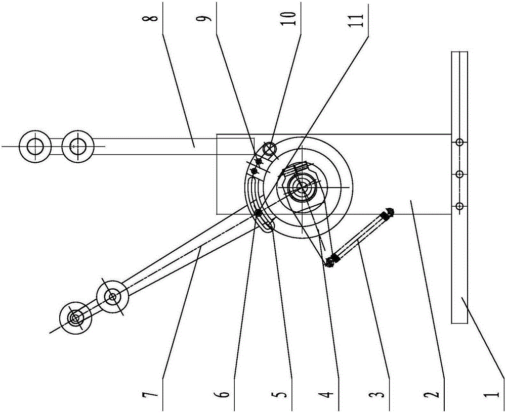
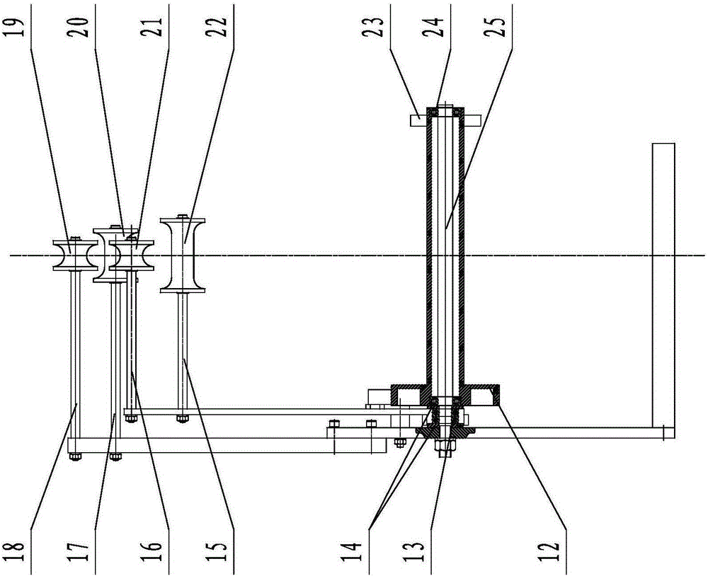
[0012] As shown in the figure: the zipper discharge device of the bag making machine in the embodiment is mainly composed of a bottom plate 1, a side plate 2, a tension spring 3, a swing arm 4, a locking seat 5, a first bearing 6, a swing rod 7, and a fixed rod 8 , brake block 9, shaft pin 10, small shaft 11, roller 12, second bearing 13, bearing limit ring 14, first moving guide roller shaft 15, second moving guide roller shaft 16, first fixed guide roller shaft 17. The second fixed guide roller shaft 18, the second fixed guide roller 19, the first fixed guide roller 20, the second moving guide roller 21, the first moving guide roller 22, the retaining ring 23, the third bearing 24 and the roller Shaft 25 and other components are formed.

[0013] Such as figure 1 , figure 2 As shown, the side plate 2 is fixed on the bottom plate 1 with screws, one end of ...


PUM


Abstract

The invention relates to a zipper discharging device for a bag making machine. A side plate is fixed to a bottom plate. One end of a roller shaft is installed on the side plate. A roller is installed on the roller shaft through a third bearing in a supported manner. A blocking step is arranged at one end of the roller. A blocking ring is installed at the other end of the roller. One end of a swing rod is connected to the roller shaft through a second bearing. A first movable guide roller and a second movable guide roller are installed at the other end of the swing rod. One end of a swing arm is fixed to the swing rod, and the other end of the swing arm is connected with the side plate through a tension spring. The rear end of a locking base is hinged to the side plate, a long groove is formed in the front portion of the locking base, and the distance between the center of the long groove and the rotary center of the roller shaft is gradually increased from the back to the front. A brake block is fixedly installed in the middle of the locking base. A small shaft is installed on the swing rod and penetrates the interior of the long groove in the locking base. A fixed rod is fixedly installed on the side plate, and a first fixed guide roller and a second fixed guide roller are installed at the upper end of the fixed rod. Zippers can keep proper tension in the discharging process, the discharging effect is good, working efficiency is improved, and labor intensity is relieved.

Description

technical field [0001] The invention relates to a zipper discharging device, in particular to a zipper discharging device for a bag making machine, belonging to the technical field of bag making machines. Background technique [0002] With the continuous development of the economy, the market's functional requirements for bag making machines are becoming higher and higher, such as more and more packaging bags are required to have a zipper sealing function. Although the bag making machines currently on the market can realize the production of zipper packaging bags, the zipper feeding effect is poor, resulting in low work efficiency and affecting the production efficiency and market competitiveness of enterprises. Contents of the invention [0003] The purpose of the present invention is to overcome the deficiencies in the prior art, and provide a zipper discharge device for bag making machines, which has a compact structure and simple operation, can keep the zipper at a sui...

Claims


Application Information

Patent Timeline
IPC IPC(8): B65H49/18
Inventor 郭林
Owner WUXI KING MO MACHINERY
Why Eureka
Try Eureka