Detector and detection method of elevator overload protection device
An overload protection and detector technology, applied in the direction of measuring devices, machine/structural components testing, instruments, etc., can solve the problems of reduced use efficiency, high inspection cost, overloaded elevator operation, etc., to save adjustment time and improve inspection speed. , the effect of improving the applicability
- Summary
- Abstract
- Description
- Claims
- Application Information
AI Technical Summary
Problems solved by technology
Method used
Image
Examples
Embodiment 1
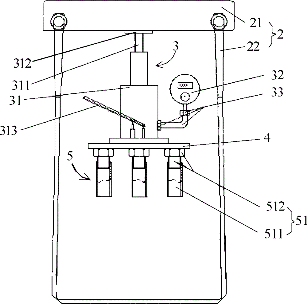
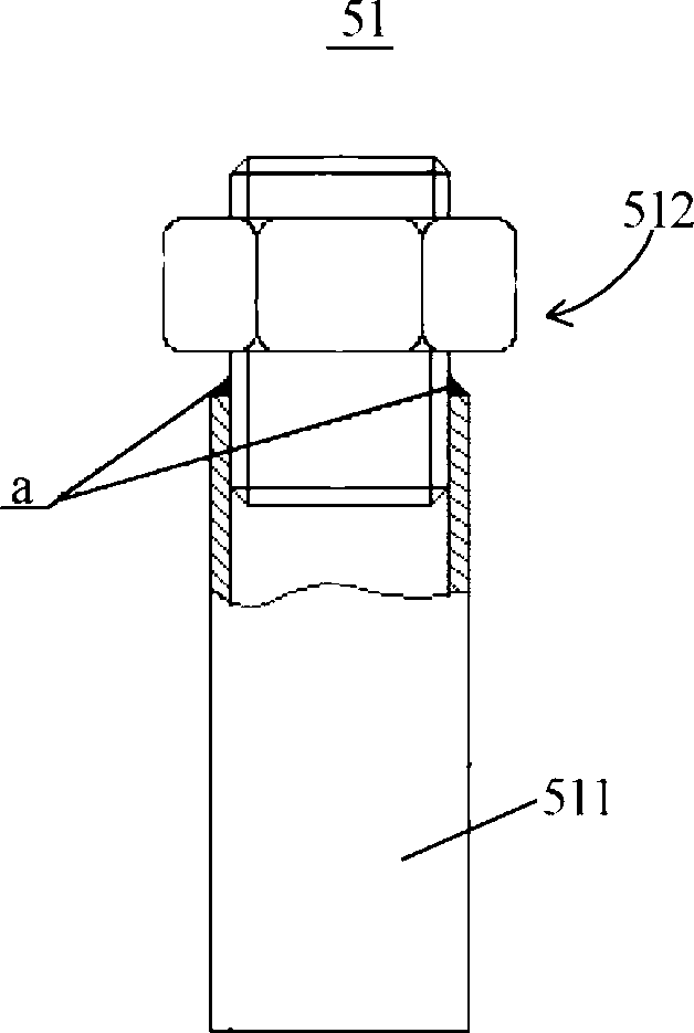
[0046] Figure 2A It is a structural schematic diagram of a detector for an elevator overload protection device according to Embodiment 1 of the present invention, referring to Figure 2A , The detector includes a suspension mechanism 2, a hydraulic mechanism 3, a base plate 4 and an adjustable bushing group 5, which will be described separately below.
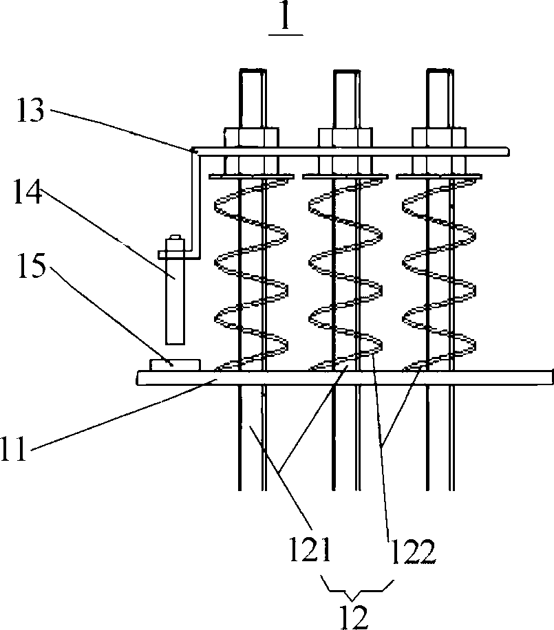
[0047] refer to Figure 2A , the suspension mechanism 2 includes a suspension 21 and a sling 22 , and the hydraulic mechanism 3 includes a hydraulic jack 31 and a pressure detector 32 . Wherein, the sling 22 is used to limit the rope head plate of the suspension 21 relative to the elevator (such as figure 1 The furthest distance of the rope head plate 11) shown, when the detector is working, the furthest distance is preserved between the suspension 21 and the rope head plate. The suspension 21 is used to provide support for the hydraulic jack 31 when it is working. Specifically, the top end of the adjustment screw 311 of th...
Embodiment 2
[0054] image 3 It is a schematic diagram of the application of the detector according to Embodiment 1 of the present invention, such as image 3 As shown, the suspension 21 of the suspension mechanism 2 is in the shape of a rectangle as a whole, and through holes 211 are provided at both ends thereof. After the sling 22 passes around the bottom of the rope head plate 11, its two ends are fixed on the suspension 21 by fasteners 212 (for example, bolts and nuts) that cooperate with the through holes 211, thereby limiting the suspension 21 relative to the rope head. The furthest distance from the board 11. Since the adjusting screw 311 abuts against the suspension 21 through the top plate 312, the sling 22 can be tightened by adjusting the height of the adjusting screw 311, so that the suspension 21 remains at the farthest distance from the rope head plate 11 .
[0055] In this embodiment, the detector can perform high-precision detection of the overload protection device wit...
Embodiment 3
[0057] Figure 4 It is a schematic diagram of the application of the detector according to Embodiment 3 of the present invention. In this embodiment, except for the features specified below, other features of the detector may be the same or similar to those of the detector in Embodiment 1.
[0058] Such as Figure 4 As shown, the suspension 21 of the suspension mechanism 2 includes a beam 213 for abutting against the top plate 312 above the hydraulic jack 31 , and extensions 214 extending vertically from both ends of the beam 213 . A row of through holes 211 are respectively arranged on the two extensions 214, and are used to cooperate with fasteners 212 to fix the two ends of the sling 22 passing around the bottom of the rope head plate 11 and the pad 16 to the suspension 21, Thus, the farthest distance of the suspension 21 relative to the rope head plate 11 is limited. Since rows of through holes 211 are provided on the extension 214, the fixed position of the sling 22 on ...
PUM
 Abstract
Description
Claims
Application Information
 - R&D
- Intellectual Property
- Life Sciences
- Materials
- Tech Scout
- Unparalleled Data Quality
- Higher Quality Content
- 60% Fewer Hallucinations
Browse by: Latest US Patents, China's latest patents, Technical Efficacy Thesaurus, Application Domain, Technology Topic, Popular Technical Reports.
© 2025 PatSnap. All rights reserved.Legal|Privacy policy|Modern Slavery Act Transparency Statement|Sitemap|About US| Contact US: help@patsnap.com


