A detection instrument and detection method for an elevator overload protection device

A technology of overload protection and detector, which is applied in the direction of measuring device, machine/structural component test, instrument, etc. It can solve the problems of high detection cost, reduced use efficiency, and difficult transportation, so as to improve detection speed, save adjustment time, The effect of high safety factor

Inactive Publication Date: 2018-07-03
嘉兴市特种设备检验检测院
View PDF6 Cites 0 Cited by
  • Summary
  • Abstract
  • Description
  • Claims
  • Application Information

AI Technical Summary

Problems solved by technology

If the overload action value is too small, the elevator will prompt overload when it is not full, which reduces the use efficiency and affects the user's use; if the overload action value is too large or the overload protection device fails completely (for example, the overload protection device is damaged), it will cause the elevator to Overload operation, forming a serious safety hazard
[0005] The existing loading detection method has the following defects: since the rated load of the elevator is usually measured in tons, the total weight of the weights is relatively large and difficult to transport; during the detection process, it is necessary to manually carry the weights into the car, and end After that, the weight needs to be removed from the car
The above factors lead to the high detection cost of the existing loading detection method (for example, the rental fee of the weight, the transportation fee, etc.), the labor intensity is high, and the detection efficiency is low.
[0006] Therefore, the market urgently needs a simple and efficient detection instrument and method to replace the existing loading detection method, but through consulting domestic and foreign literature, the applicant did not find any record of a special instrument used to detect the elevator overload device

Method used


Image

  • A detection instrument and detection method for an elevator overload protection device
  • A detection instrument and detection method for an elevator overload protection device
  • A detection instrument and detection method for an elevator overload protection device

Examples


Embodiment 1

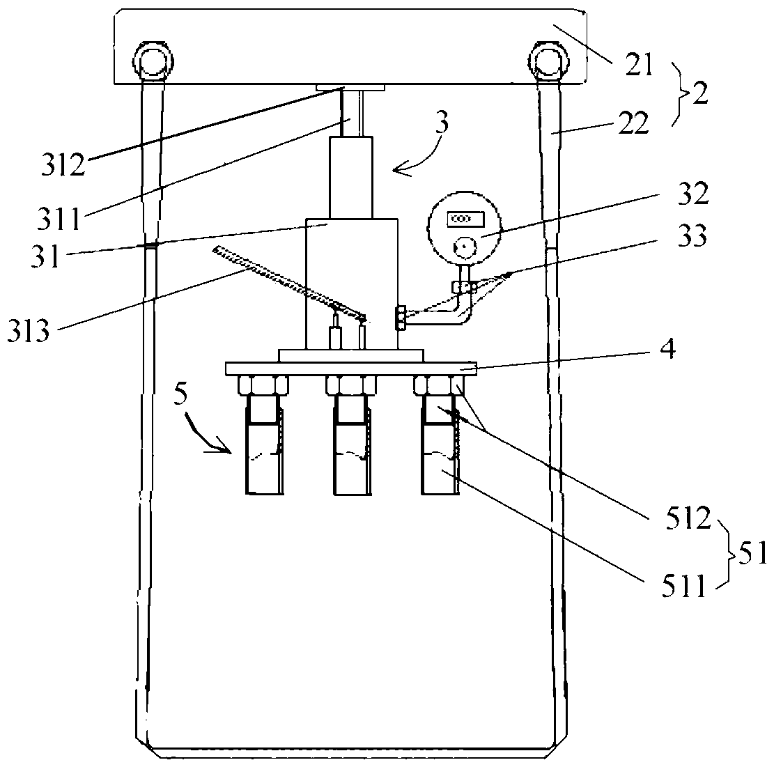
[0046] Figure 2A It is a structural schematic diagram of a detector for an elevator overload protection device according to Embodiment 1 of the present invention, referring to Figure 2A , The detector includes a suspension mechanism 2, a hydraulic mechanism 3, a base plate 4 and an adjustable bushing group 5, which will be described separately below.

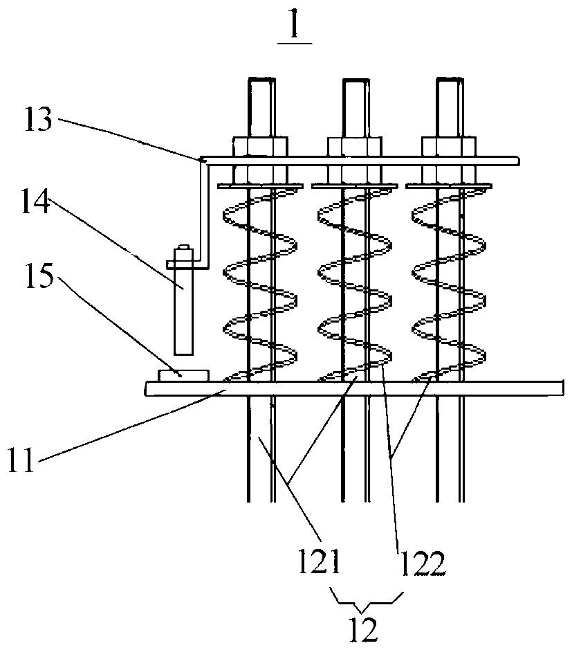
[0047] refer to Figure 2A , the suspension mechanism 2 includes a suspension 21 and a sling 22 , and the hydraulic mechanism 3 includes a hydraulic jack 31 and a pressure detector 32 . Wherein, the sling 22 is used to limit the rope head plate of the suspension 21 relative to the elevator (such as figure 1 The furthest distance of the rope head plate 11) shown, when the detector is working, the furthest distance is preserved between the suspension 21 and the rope head plate. The suspension 21 is used to provide support for the hydraulic jack 31 when it is working. Specifically, the top end of the adjustment screw 311 of th...

Embodiment 2

[0054] image 3 It is a schematic diagram of the application of the detector according to Embodiment 1 of the present invention, such as image 3 As shown, the suspension 21 of the suspension mechanism 2 is in the shape of a rectangle as a whole, and through holes 211 are provided at both ends thereof. After the sling 22 passes around the bottom of the rope head plate 11, its two ends are fixed on the suspension 21 by fasteners 212 (for example, bolts and nuts) that cooperate with the through holes 211, thereby limiting the suspension 21 relative to the rope head. The furthest distance from the board 11. Since the adjusting screw 311 abuts against the suspension 21 through the top plate 312, the sling 22 can be tightened by adjusting the height of the adjusting screw 311, so that the suspension 21 remains at the farthest distance from the rope head plate 11 .

[0055] In this embodiment, the detector can perform high-precision detection of the overload protection device wit...

Embodiment 3

[0057] Figure 4 It is a schematic diagram of the application of the detector according to Embodiment 3 of the present invention. In this embodiment, except for the features specified below, other features of the detector may be the same or similar to those of the detector in Embodiment 1.

[0058] Such as Figure 4 As shown, the suspension 21 of the suspension mechanism 2 includes a beam 213 for abutting against the top plate 312 above the hydraulic jack 31 , and extensions 214 extending vertically from both ends of the beam 213 . A row of through holes 211 are respectively arranged on the two extensions 214, and are used to cooperate with fasteners 212 to fix the two ends of the sling 22 passing around the bottom of the rope head plate 11 and the pad 16 to the suspension 21, Thus, the farthest distance of the suspension 21 relative to the rope head plate 11 is limited. Since rows of through holes 211 are provided on the extension 214, the fixed position of the sling 22 on ...


PUM


Abstract

The invention provides a detector and a detection method for an elevator overload protection device, wherein the detector includes: a suspension mechanism, including a suspension and a lifting belt for limiting the farthest distance of the suspension relative to the rope head plate The hydraulic mechanism includes a hydraulic jack and a pressure detector. The top of the adjusting screw of the hydraulic jack has a top plate for abutting against the suspension, so that the hydraulic jack uses the suspension as a support to apply a load when the hydraulic jack is working. The pressure detector is used to detect the hydraulic jack. The value of the applied load; the base plate, located below the hydraulic jack, is used to transmit the load applied by the hydraulic jack; the adjustable bushing set, located under the base plate, has a plurality of adjustable bushings, and one end of each adjustable bushing has The sleeve used for sheathing the rope head rod has an adjustment mechanism at the other end for adjusting the height of the adjustable sleeve. By adopting the invention, the overload protection device can be detected with high efficiency and high precision with reasonable structure and simple and convenient operation.

Description

technical field [0001] The invention relates to the detection field of an elevator overload protection device, in particular to a detector and a detection method of an elevator overload protection device. Background technique [0002] The elevator overload protection device is a very important safety protection device in the passenger and cargo elevators, and its detection is an important inspection item related to the safety of passengers and goods on the elevator. The General Administration of Quality Supervision, Inspection and Quarantine of the People's Republic of China "Elevator Supervision Inspection and Periodic Inspection Rules - Traction and Forced Drive Elevators" stipulates that for newly installed and annual inspection elevators, loading tests should be carried out to verify the function of overload protection devices. [0003] The working principle of the elevator overload protection device: When the load in the elevator car exceeds 110% of the rated load (the ...

Claims


Application Information

Patent Timeline
Patent Type & Authority Patents(China)
IPC IPC(8): B66B5/00G01M99/00
Inventor 庞涛祝新伟苏万斌顾国明朱建新朱卫峰潘金平徐强明过鹏程陈建伟胡胜江李伟勇潘以军徐涛李方舟陈锴金晓行
Owner 嘉兴市特种设备检验检测院
Why Eureka
Try Eureka