Prefabricated continuous wall unit, underground continuous wall and construction method of underground continuous wall

A technology for underground diaphragm walls and connecting steel plates, which is applied in excavation, sheet pile walls, foundation structure engineering, etc., can solve the problem of difficulty in ensuring the strength and anti-seepage performance of underground diaphragm walls and joints, inability to ensure the support effect of foundation pit engineering, cross One side of the shaped steel plate is not stable, etc., to achieve the effect of enhancing rigidity, shortening the construction period, and reducing the impact of the surrounding environment

Inactive Publication Date: 2015-12-23
JINAN RAILWAY TRANSPORT GRP CO LTD
View PDF6 Cites 6 Cited by
  • Summary
  • Abstract
  • Description
  • Claims
  • Application Information

AI Technical Summary

Problems solved by technology

However, it is difficult to ensure the strength and anti-seepage performance of the underground diaphragm wall and joints under the condition of large groundwater pressure and construction load. On the one hand, it is difficult to prevent the concrete from flowing around and the high external Under the effect of water and soil pressure, even if joint treatment devices such as lock pipes are used, the bypass flow path is only extended, and the joints are still permeable under the action of high water and soil pressure; on the other hand, continuous underground When the wall is used as the load-bearing component of the building, the existing joints are not rigid enough. For example, if the cross steel plate is used as the rigid joint componen

Method used


Image

  • Prefabricated continuous wall unit, underground continuous wall and construction method of underground continuous wall
  • Prefabricated continuous wall unit, underground continuous wall and construction method of underground continuous wall
  • Prefabricated continuous wall unit, underground continuous wall and construction method of underground continuous wall

Examples


Embodiment Construction

[0024] In order to clearly illustrate the technical features of this solution, the specific implementation of the present invention will be further described below according to the accompanying drawings.

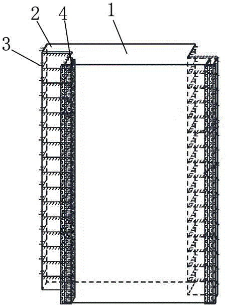
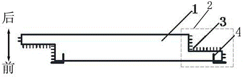
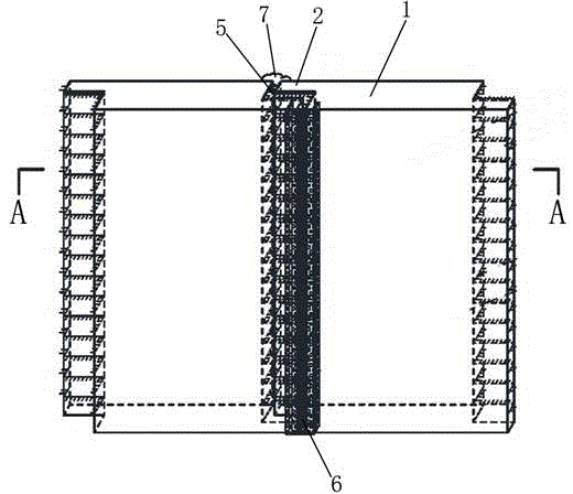
[0025] Such as figure 1 , figure 2 As shown, a prefabricated continuous wall unit includes a prefabricated continuous wall unit body 1, the thickness of the prefabricated continuous wall unit body 1 is 800mm~1200mm, and the two ends of the prefabricated continuous wall unit body 1 are provided with stepped joints 2, The joint 2 is symmetrically arranged centering on the center of the cross section of the prefabricated continuous wall unit body 1, and the surface of the joint 2 is roughened; the prefabricated continuous wall unit body 1 is provided with a steel bar 3 protruding from the surface of the joint 2, so that The steel bars 3 are HRB400 threaded steel bars, the length of one end of the steel bars 3 protruding from the surface of the joint 2 is 100mm~150mm, the stee...


PUM

PropertyMeasurementUnit
Thicknessaaaaaaaaaa

Abstract

The invention relates to the field of underground structure construction, in particular to a prefabricated continuous wall unit. The prefabricated continuous wall unit comprises a prefabricated continuous wall unit body, wherein connectors are arranged at the two ends of the prefabricated continuous wall unit body, and rebars protruding out of the surfaces of the connectors are arranged in the prefabricated continuous wall unit body; two L-shaped steel plates are arranged at the left side and the right side of the front surface of the prefabricated continuous wall unit body respectively, and the upper end and the lower end of each L-shaped steel plate are flush with the upper end and the lower end of the prefabricated continuous wall unit body respectively. The invention further provides an underground continuous wall formed by connection of at least two prefabricated continuous wall units through the connectors and the L-shaped steel plates. Compared with the prior art, the prefabricated continuous wall unit and the underground continuous wall have the beneficial effects that rigidity is high, seepage-proofing performance is high, and a good foundation pit engineering support effect, reasonable dispersion of wall shearing force transmission paths and effective prevention of underground water seepage can be guaranteed when the underground continuous wall serves as a supporting structure and a basement outer wall or an upper bearing member during reverse construction.

Description

technical field [0001] The invention relates to the field of underground structure construction, in particular to a prefabricated continuous wall unit, an underground continuous wall and a construction method thereof. Background technique [0002] With the gradual acceleration of the pace of rail transit and urbanization construction, there are more and more infrastructure constructions such as urban subways, high-speed rails, underground stations, and underground plazas. As an enclosure structure, underground diaphragm walls have also been widely used in foundation pit engineering support. development applications. At present, the underground diaphragm wall used for foundation pit support generally adopts the method of laying steel cages in the pre-constructed groove section and pouring concrete, and taking certain measures at the joints of the diaphragm wall (cross prefabricated joints, I-shaped prefabricated joints or lock joints) The groove formed by the pipe) to form a...

Claims


Application Information

Patent Timeline
IPC IPC(8): E02D5/02E02D5/14E02D17/04
Inventor 王国富温小康胡永利
Owner JINAN RAILWAY TRANSPORT GRP CO LTD
Why Eureka
Try Eureka