Combustion chamber of supersonic combustion ramjet engine

A technology of super-combustion stamping and combustion chamber, which is applied in the direction of combustion chamber, continuous combustion chamber, combustion method, etc., and can solve the problems of unfavorable cavity ignition and stable combustion, large total pressure loss of multi-cavity, and oil-rich ignition of cavity , to achieve the effects of improving flame stability, optimizing fuel equivalence ratio distribution, and improving ignition performance

Active Publication Date: 2015-12-23
NAT UNIV OF DEFENSE TECH
View PDF8 Cites 14 Cited by
  • Summary
  • Abstract
  • Description
  • Claims
  • Application Information

AI Technical Summary

Problems solved by technology

However, there are only two concave cavity schemes suitable for a wide range of Mach numbers. One is to use a combination of multiple concave cavities, combined with fuel injection to adjust the heat release area with the change of Mach number, but the total pressure loss of multiple concave cavities is large. , the internal resistance is large, and the thermal protection problem of multiple concave cavities is difficult to solve
The second is to use a mechanically adjustable device to adjust the profile of the combustion chamber as the Mach number changes, but this solution is currently difficult to apply due to its complexity
[0006] The c

Method used


Image

  • Combustion chamber of supersonic combustion ramjet engine
  • Combustion chamber of supersonic combustion ramjet engine
  • Combustion chamber of supersonic combustion ramjet engine

Examples


Embodiment Construction

[0044] The embodiments of the present invention will be described in detail below with reference to the accompanying drawings, but the present invention can be implemented in many different ways defined and covered by the claims.

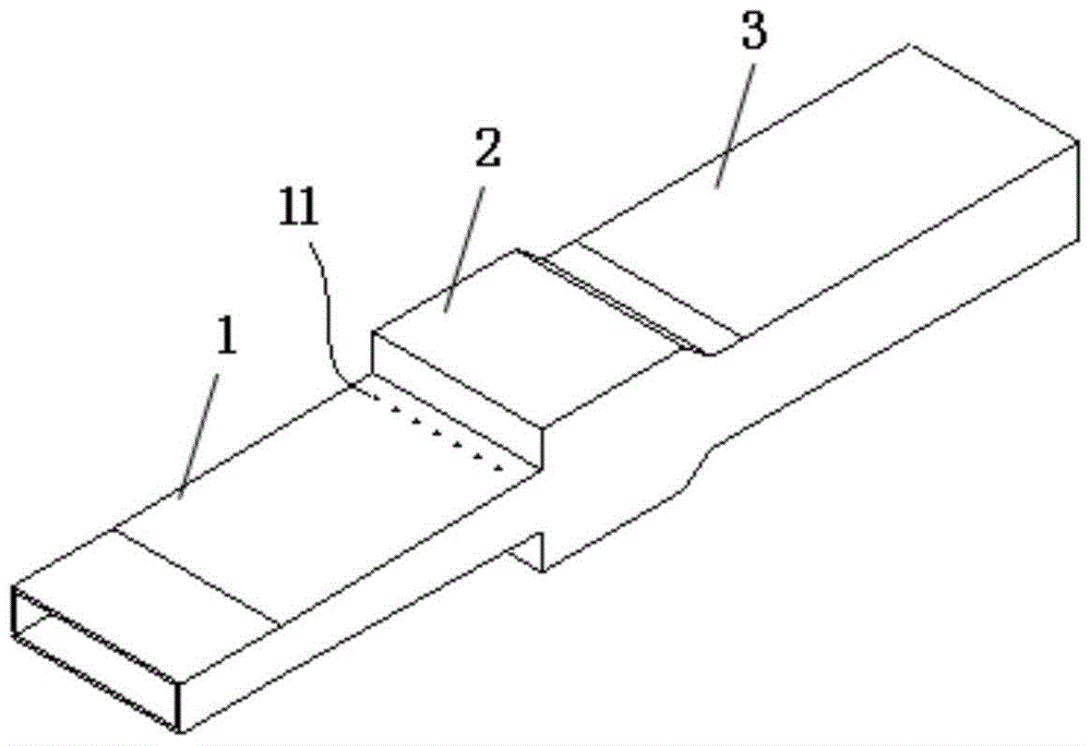
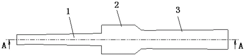
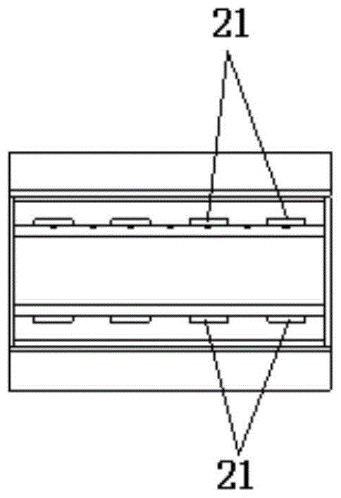
[0045] Figure 1 to Figure 7 The structure of the flared trailing edge concave cavity combustion chamber with rectangular cross-section is shown. Such as Figure 1 to Figure 7 As shown, the combustion chamber of the scramjet engine of this embodiment includes an injection section 1, a rear edge sudden expansion type concave cavity 2, and an expansion section 3, and a group of fuel injection holes 11 are horizontally arranged on the injection section 1, and also include The deflector 21 is arranged at the front edge of the rear edge of the suddenly expanding concave cavity 2 to control the development form of the shear layer.

[0046] By arranging a deflector 21 at the front edge of the trailing edge flared cavity 2, the lateral fuel injection on t...


PUM


Abstract

The invention discloses a combustion chamber of a supersonic combustion ramjet engine. The combustion chamber comprises a jet segment, a rear-edge sudden-enlargement cavity and an expansion segment, which are orderly communicated, wherein a fuel spray hole is formed in the jet segment. The combustion chamber further comprises a guide plate arranged at the front edge of the rear-edge sudden-enlargement cavity, and the guide plate is used for decreasing the amount of upstream wall fuel jet brought into the cavity by a shear layer. According to the combustion chamber, through the rear-edge sudden-enlargement cavity with the guide plate, the transverse jet of upstream wall fuel is not directly brought into the cavity by the shear layer; the mass flow rate of the flue entering the cavity is changed by adjusting the transverse space of the guide plate, therefore the equivalent ratio distribution of flue in the cavity and outside the cavity is optimized, the ignition performance in the cavity is improved, and the flame holding capacity of the cavity is improved.

Description

technical field [0001] The invention relates to the field of engine combustion control, in particular to a combustion chamber of a scramjet engine. Background technique [0002] Concave flame stabilizers are widely used in scramjet combustion chambers. The supersonic airflow flowing through the concave cavity will form a recirculation zone in the concave cavity, which can keep the flame in it all the time, and continue to ignite the upstream fuel as a new ignition source, so as to achieve flame stabilization. The concave cavity can integrate fuel injection, mixing enhancement and flame stabilization in the supersonic combustion chamber, and plays an important role in improving the performance of the scramjet engine. [0003] Fuel injection / ignition / flame stabilization / cooling integrated concave cavity, which is common in engineering at present, includes the integration of fuel injection, ignition, and flame stabilization, with the concave cavity as the basic configuration, ...

Claims


Application Information

Patent Timeline
IPC IPC(8): F23R3/26
Inventor 孙明波蔡尊王振国
Owner NAT UNIV OF DEFENSE TECH
Why Eureka
Try Eureka