Burner with high flame stability

a burner and flame stability technology, applied in the direction of combustion types, machines/engines, lighting and heating apparatus, etc., can solve the problems of unstable flame front, dangerous operation near flame extinction limit, and reduced flame speed

Inactive Publication Date: 2002-11-21
ANSALDO ENERGIA SWITZERLAND AG
View PDF5 Cites 13 Cited by
  • Summary
  • Abstract
  • Description
  • Claims
  • Application Information

AI Technical Summary

Problems solved by technology

Although such burners make possible an operation with very low pollutant emissions, they often operate dangerously near to the extinction limit of the flame.
This reduces the flame speed, which in turn results in a flame front which is widely expanded spatially and is...

Method used


Image

  • Burner with high flame stability
  • Burner with high flame stability
  • Burner with high flame stability

Examples


Embodiment Construction

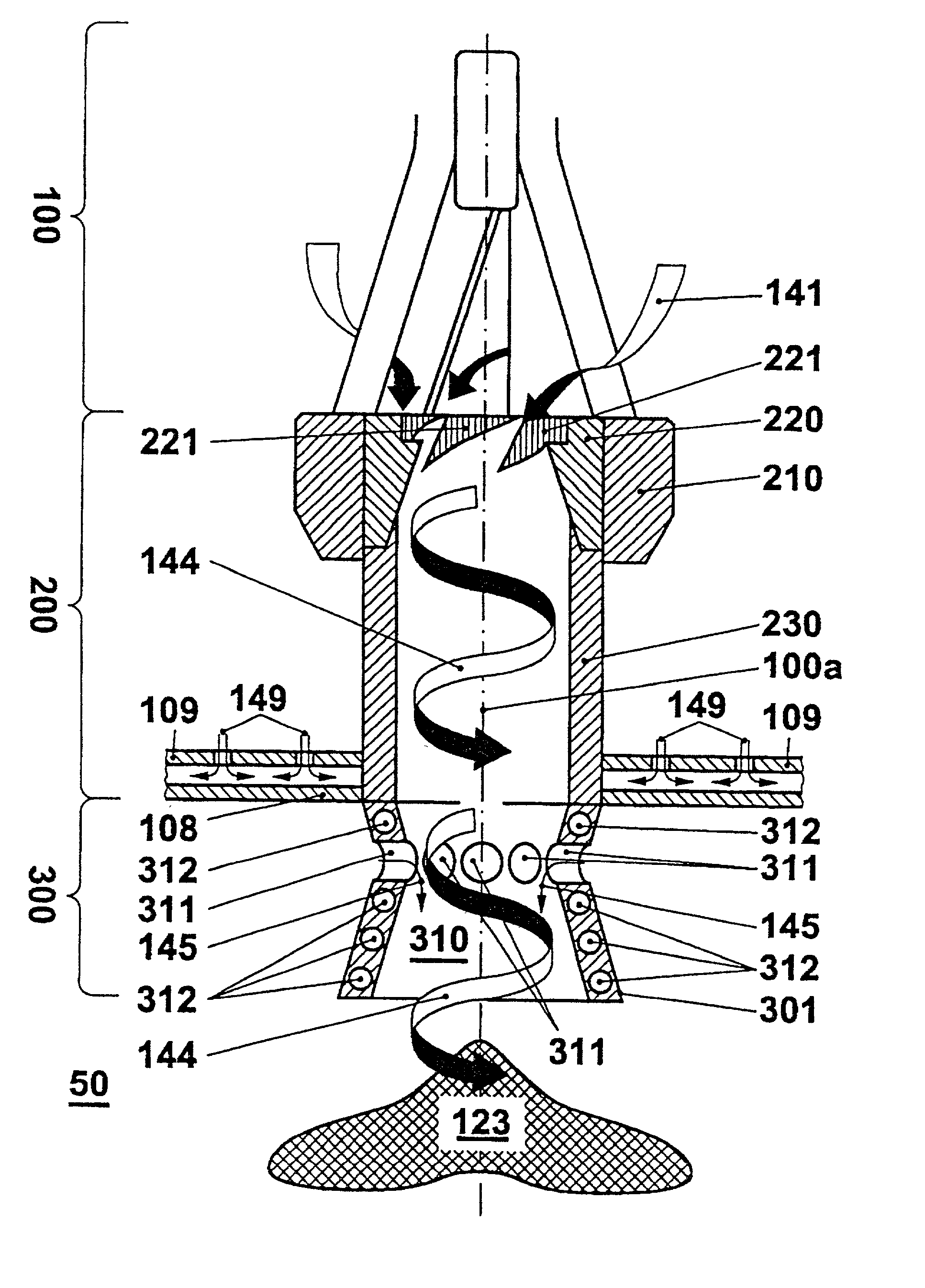
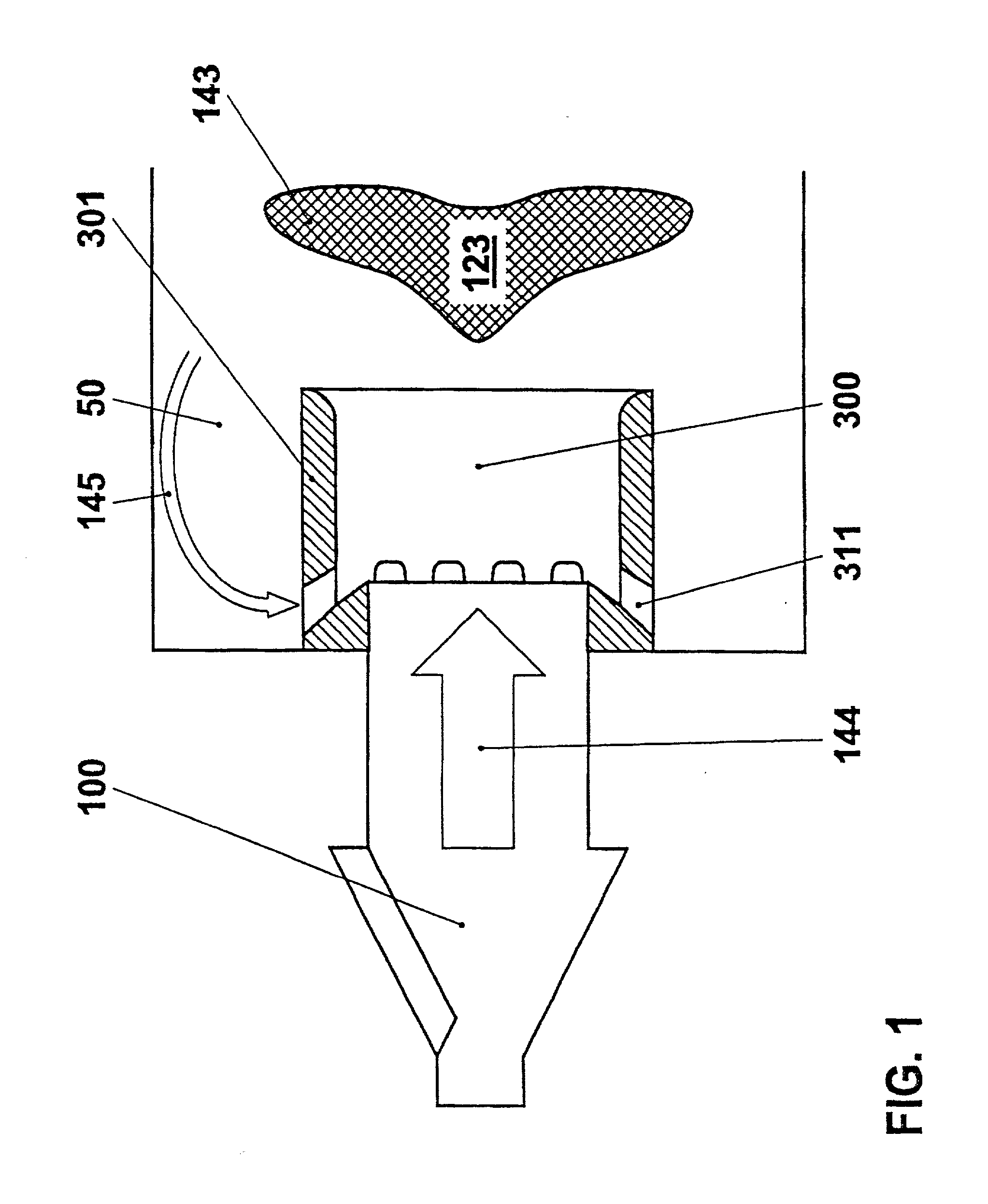
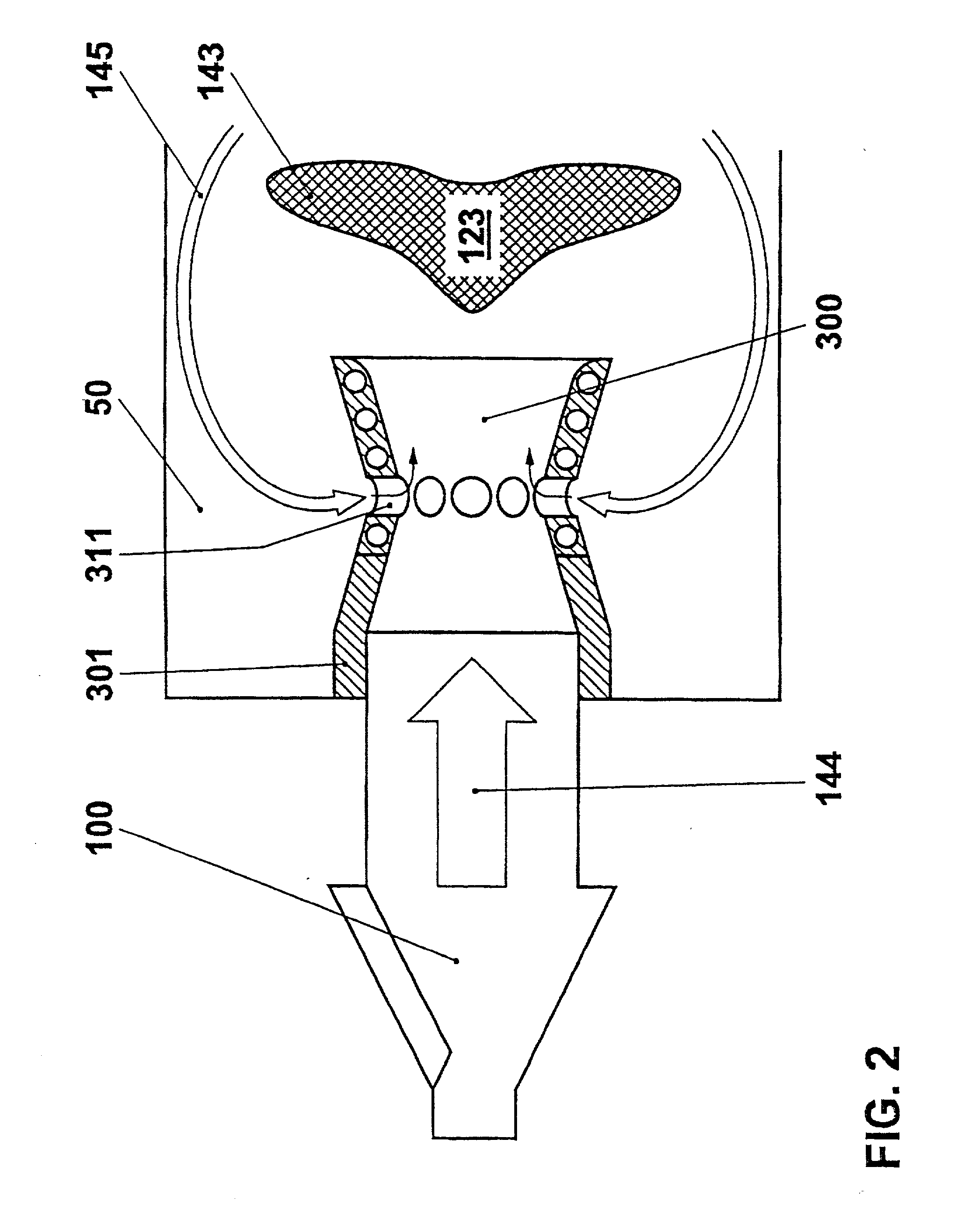
[0017] FIGS. 1 and 2 reproduce, very schematically, the essence of the invention. Initially the swirl producer 100 is effective; its possibilities of embodiment are discussed in further detail in the following FIGS. 3-5. As is shown there, a premix burner, known per se, can be concerned for this swirl producer 100, as is described, among other things, in the publications cited in this explanation. These burners, cited by way of example, are all based on a common principle. They have an axially extending, at least approximately rotationally symmetrical cavity 122, into which combustion air flows through inlet slots 121 running preferably parallel to the longitudinal axis. The combustion air receives a strong tangential speed component from the tangential alignment of these more or less slot-shaped inlet apertures 121, resulting in a swirl flow through the said internal space (122) from the reciprocal action of the said tangential component with the axial components directed toward th...


PUM


Abstract

The invention relates to a premix burner with high flame stability for use in a heat producer, preferably in the combustion chamber of a gas turbine. Modem lean operated premix burners make possible very low pollutant emissions, but sometimes operate very close to the extinction limit. To increase the stability of the lean premix combustion by increasing the distance between the flame temperature and the extinction limit temperature, it is proposed according to the invention to arrange a downstream combustion gas mixing section (300) for the burner, which mixing section (300) projects at least partially into the combustion chamber (50) and enables combustion gases from the combustion chamber (50) access to the fuel/air mixture (144) by means of combustion gas inlet openings (311). The added combustion gases (145) are mixed with the fuel/air mixture (144), and in this manner increase its temperature. This increase in temperature results in a significant increase in the flame speed, as a consequence of which the extent of the flame front (123) and the extinction limit temperature of the burner decrease.

Description

[0001] The invention describes a burner for a heat producer according to the preamble of claim 1.DESCRIPTION OF PRIOR ART[0002] Premix burners are known from EP 0 321 809, EP 0 780 629, WO 9317279, as well as EP 0 945 677; in them, a combustion air stream is introduced tangentially into the interior of a burner by means of a swirl producer, and is mixed with fuel. At the burner outlet, the vortex flow which arises bursts open at a sudden change of cross section, with the initiation of a back-flow zone which serves to stabilize a flame in the operation of the burner.[0003] Although such burners make possible an operation with very low pollutant emissions, they often operate dangerously near to the extinction limit of the flame. Flame temperatures usually obtained with the lean premix flames of such burners are about 1,700-1,750 K. The extinction limit of the flame is given as about 1,650 K. This value is comparatively high. This is based on the low fuel ratio in the fuel-air mixture....

Claims


Application Information

Patent Timeline
IPC IPC(8): F23C7/00F23C9/00F23D11/40F23D14/62F23D14/78
CPCF23C7/002F23C9/006F23C2900/07002F23D2212/10F23D14/62F23D14/78F23D2206/10F23D11/402
Inventor RUCK, THOMASKNOEPFEL, HANS PETER
Owner ANSALDO ENERGIA SWITZERLAND AG
Why Eureka
Try Eureka