Energy efficient low NOx burner and method of operating same

a burner and low nox technology, applied in the field of fuel gas burners, can solve the problems of reducing control, reducing the efficiency of combustion products, so as to achieve the effect of improving flame stability and reducing the nox level

Active Publication Date: 2005-12-08
JOHN ZINK CO LLC
View PDF3 Cites 16 Cited by
  • Summary
  • Abstract
  • Description
  • Claims
  • Application Information

AI Technical Summary

Benefits of technology

[0014] The present invention provides a burner assembly that emits a lower level of NOx, is energy-efficient and has improved flame stability. The burner assembly is placed inside the radiant section of a boiler near its front wall. The main component of the burner is an open-ended cylinder open at its distal end. A plurality of combustion air ports extend into the cylinder from a proximal end of the cylinder and are coupled to a source of combustion air. The source of combustion air may supply a mixture of combustion air and flue gas from the boiler stack. The burner assembly further comprises a plurality of fuel gas discharge nozzles extending into the cylinder from its proximal end that are coupled to a fuel source. Finally, the burner assembly comprises a plurality of furnace gas openings defined in the cylinder and spaced around the cylinder's circumference at the boiler front wall. The diameter of the cylinder varies with the burner design capacity, furnace cross section and other design parameters like the required burner turndown, limits on the air pressure losses as it passes through the burner and some other factors. The length of the cylinder typically varies between one and two cylinder diameters depending on the furnace length and some other parameters.

Problems solved by technology

At the same time, however, recirculation of the flue gas substantially increases the energy required for passing the mixture flow of combustion air and added flue gas through the system.
So the effectiveness of this gas for the purpose of flame temperature reduction and NOx control is diminished.
This makes it more difficult to return a substantial portion of combustion products back to the burner.
In addition to the factor of increased operating costs of burners with high amounts of FGR, another problem in achieving very low NOx levels, typically below 10 ppm, is maintaining a stable flame without strong oscillations.

Method used


Image

  • Energy efficient low NOx burner and method of operating same
  • Energy efficient low NOx burner and method of operating same
  • Energy efficient low NOx burner and method of operating same

Examples


Embodiment Construction

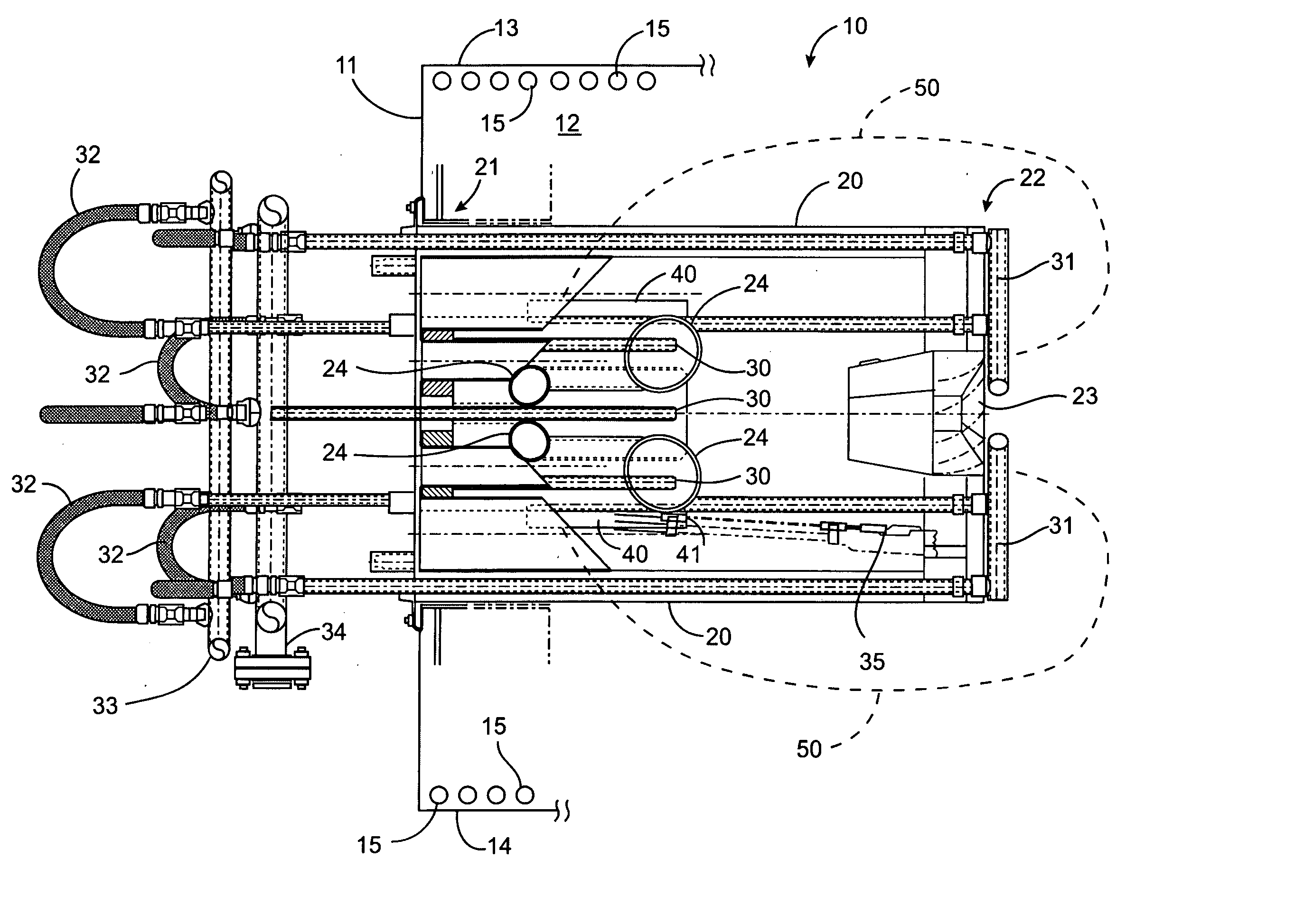
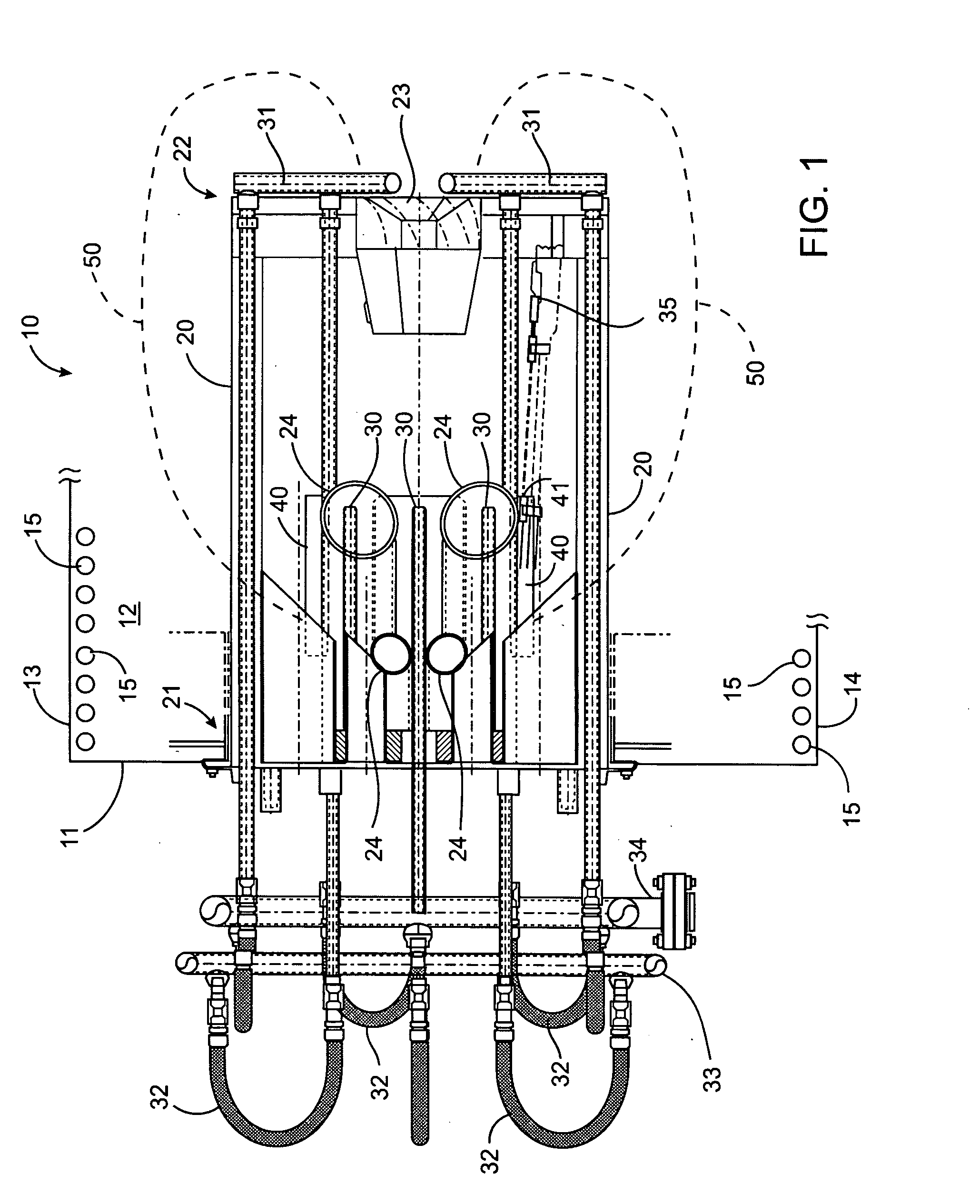
[0028] With reference to FIG. 1, a burner assembly 10 in accordance with the present invention is mounted to a furnace front wall 11 that defines a combustion chamber 12 along with two side walls (not shown), a top wall 13, and a bottom wall 14. The burner assembly projects downstream into the combustion chamber. At least some of the chamber walls are cooled by a heat transfer media. In a preferred embodiment, the walls are comprised of pipes 15 and the heat transfer media is water. These pipes, due to the heat transfer media, absorb heat from the flame and gasses within the combustion chamber.

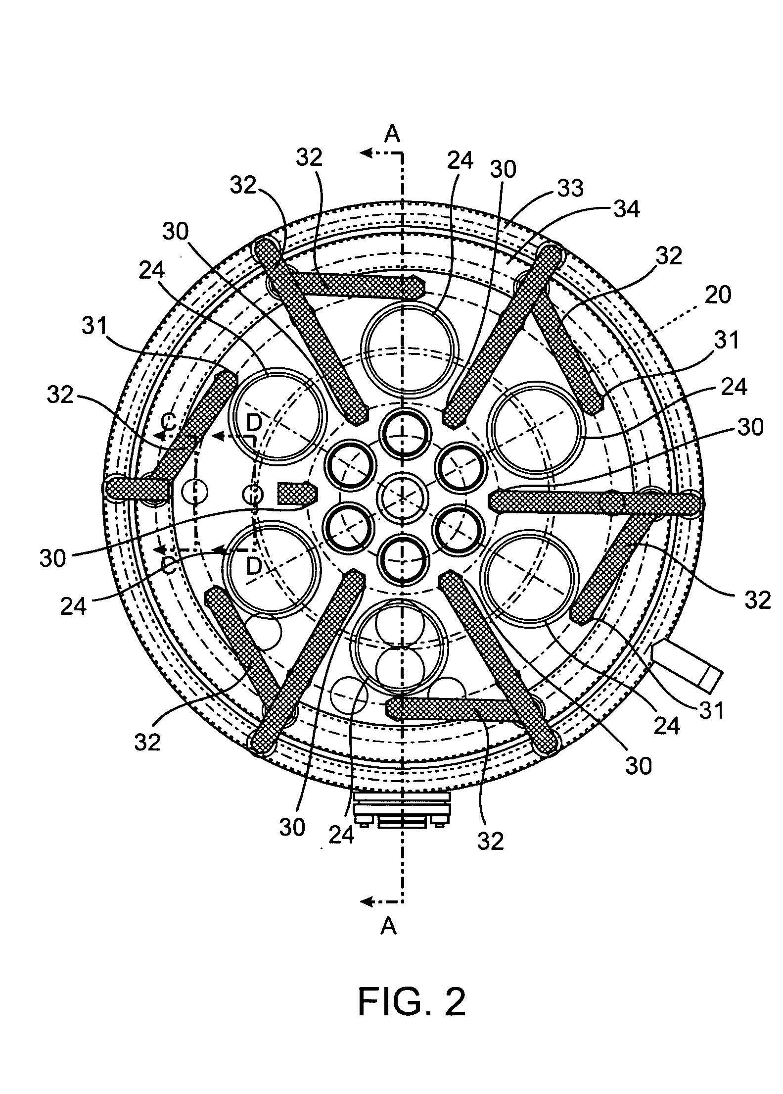
[0029] Burner assembly 10 includes a cylindrical body 20 mounted on one end to the furnace front wall 11. This end of the cylinder includes a plurality of combustion air ports 24 extending from an air source, generally the wind box of the burner assembly (not shown), through the thickness of the furnace front wall so that combustion air flows through ports 24 into cylindrical body 20. Prefera...


PUM


Abstract

A burner assembly that produces very low NOx emissions includes a plurality of furnace gas openings for receiving a portion of furnace gasses back into a combustion cylinder. The burner assembly includes the combustion cylinder, a plurality of combustion air inlet conduits that extend into the cylinder and a plurality of fuel gas discharge nozzles that also extend into the cylinder. The burner assembly is mounted within a combustion chamber of a furnace, wherein the walls of the combustion chamber are provided with or are made up of heat transfer pipes. Thus, in operation, furnace gasses exit the combustion cylinder and, due to combined aspirating action created by air jets as they exit the air conduits and fuel gas jets discharging from the fuel gas discharge nozzles inside the combustion cylinder and a pressure differential between the combustion cylinder and the combustion chamber, a portion of the furnace gasses flow from the outlet of the combustion cylinder and past the heat transfer pipes toward the proximal or upstream end of the combustion cylinder. Passage of the furnace gasses past the heat transfer pipes cools the furnace gasses and the furnace gasses then flow through the furnace gas openings and mix with the combustion air and fuel gas to provide a lower NOx emission in an energy-efficient manner.

Description

CROSS-REFERENCES TO RELATED APPLICATIONS [0001] This application is a non-provisional application and claims the benefit of Application No. 60 / 547,924, filed Feb. 25, 2004, entitled “Energy Efficient Low NOx Burner And Method Of Operating Same” (Attorney Docket No. 002139-013600US), the disclosure of which is incorporated herein by reference for all purposes.STATEMENT AS TO RIGHTS TO INVENTIONS MADE UNDER FEDERALLY SPONSORED RESEARCH OR DEVELOPMENT [0002] Not Applicable REFERENCE TO A “SEQUENCE LISTING,” A TABLE, OR A COMPUTER PROGRAM LISTING APPENDIX SUBMITTED ON A COMPACT DISK [0003] Not Applicable BACKGROUND OF THE INVENTION [0004] 1. Field of the Invention [0005] The present invention relates to fuel gas burners that have very low NOx emissions and, in particular, to such burners that operate with flue gas recirculated into the combustion chamber. [0006] 2. Description of the Prior Art [0007] There are three basic sources / mechanisms of NOx formation during the process of flame c...

Claims


Application Information

Patent Timeline
Patent Type & Authority Applications(United States)
IPC IPC(8): F23C9/00F23C6/04F23D14/64F23M3/00
CPCF23C6/047F23C9/006F23C2900/09002F23D14/64F23D2900/00008
Inventor LIFSHITS, VLADIMIR
Owner JOHN ZINK CO LLC
Why Eureka
Try Eureka