Electric heating furnace
A technology for electric heaters and power supplies, applied in the field of electric heaters, can solve problems such as unfavorable environmental protection, polluted air, inconvenient movement, etc., and achieve the effects of efficient release of heat efficiency, convenient movement, and simple structure
- Summary
- Abstract
- Description
- Claims
- Application Information
AI Technical Summary
Problems solved by technology
Method used
Image

Examples
Embodiment Construction
[0019] The present invention will be further described below in conjunction with the accompanying drawings and specific embodiments.
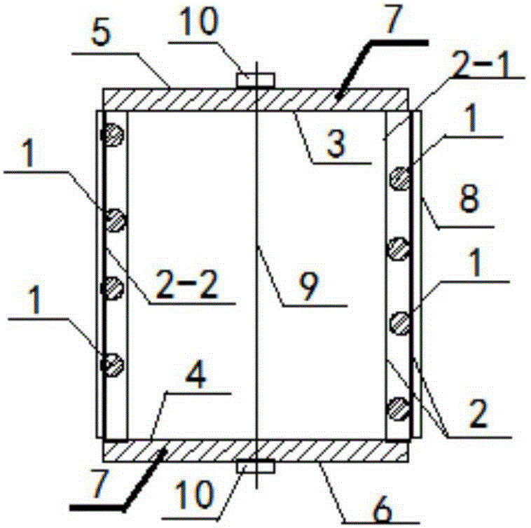
[0020] figure 1 A schematic structural view of the electric heater of the present invention is shown. Such as figure 1 As shown, the electric heater includes a heating element 1, a sealing body 2, a first sealing cover 3 and a second sealing cover 4, wherein the sealing body 2 includes an inner layer 2-1 and an outer layer 2-2, the The heating element 1 is spirally arranged between the inner layer 2-1 and the outer layer 2-2 and is in close contact with the outer layer 2-2. When the heating element 1 generates heat, it will transfer heat to the outer layer 2-2. The outer layer 2-2, the outer layer 2-2 can dissipate heat evenly, and because the heating element 1 is arranged in a spiral, the heating element 1 can generate heat evenly, instead of being limited to a certain place for heat dissipation , making heating efficient. The first sealin...
PUM
 Abstract
Description
Claims
Application Information