
A compressor exhaust temperature control method and system for a low-temperature enthalpy-injecting strong heat unit

A temperature control method and temperature control system technology, applied in refrigeration and liquefaction, refrigerators, refrigeration components, etc., can solve problems beyond safety, fluctuations, large fluctuations in compressor discharge temperature, etc., and achieve the effect of avoiding potential safety hazards

Active Publication Date: 2018-11-30
GREE ELECTRIC APPLIANCES INC
View PDF6 Cites 0 Cited by
  • Summary
  • Abstract
  • Description
  • Claims
  • Application Information

AI Technical Summary

Problems solved by technology

[0002] Low-temperature enthalpy-injection high-heat units generally use the method of injecting refrigerant into the scroll compression chamber of the compressor to improve the heating capacity of the unit at ultra-low ambient temperature, but the unit that adopts this method often has compressor discharge. The gas temperature fluctuates greatly, and sometimes even exceeds the safe fluctuation range, which brings hidden dangers to the safe operation of the unit

Method used


Image

  • A compressor exhaust temperature control method and system for a low-temperature enthalpy-injecting strong heat unit
  • A compressor exhaust temperature control method and system for a low-temperature enthalpy-injecting strong heat unit
  • A compressor exhaust temperature control method and system for a low-temperature enthalpy-injecting strong heat unit

Examples


Embodiment 1

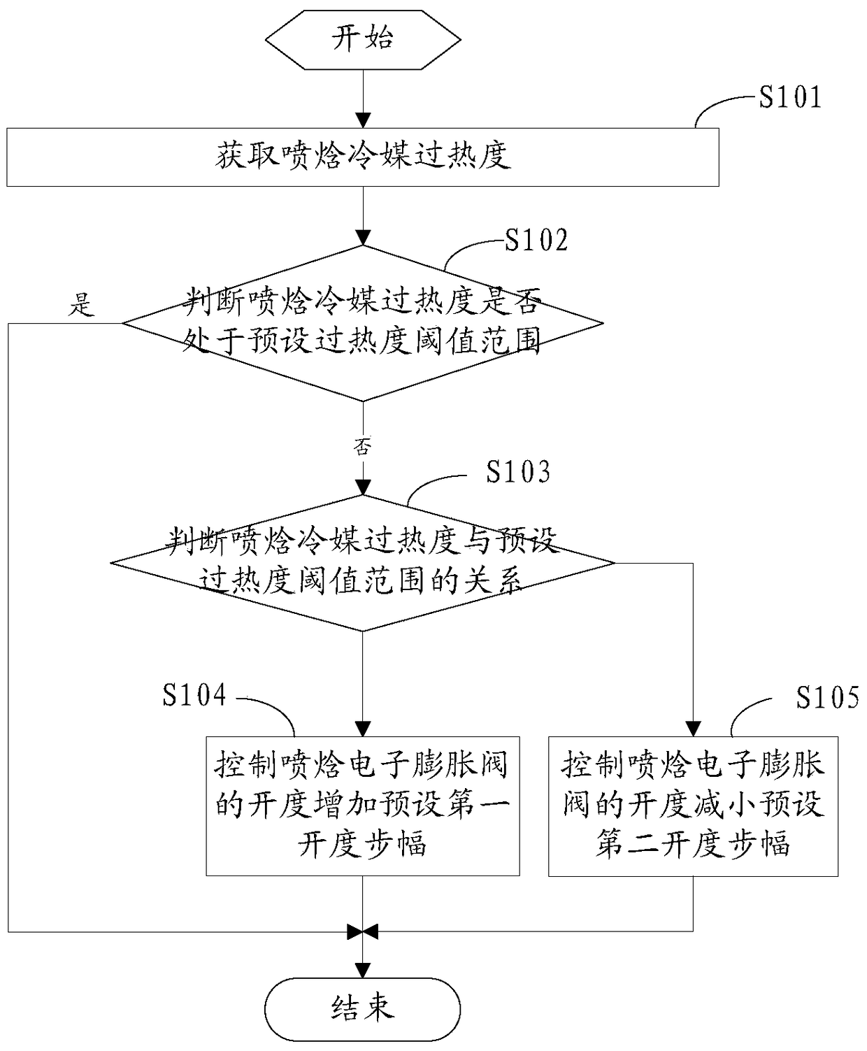
[0050] figure 1 This is a flowchart of a method for controlling the compressor discharge temperature of a low-temperature enthalpy-injection heat unit provided by an embodiment of this application.

[0051] Such as figure 1 As shown, the compressor exhaust temperature control method provided in this embodiment is applied to the controller of the low-temperature enthalpy injection heat unit, and includes the following steps:

[0052] S101: Obtain the superheat of the spray enthalpy refrigerant.

[0053] Firstly, the superheat of the spray enthalpy refrigerant is obtained through the spray pressure of the refrigerant spray port and the actual temperature.

[0054] S102: Determine whether the superheat of the injection enthalpy refrigerant is within a preset superheat threshold range.

[0055] The preset superheat threshold range is a preset superheat range, and the specific value range is selected according to actual measurement and empirical formulas. Judging whether it is within the pr...

Embodiment 2

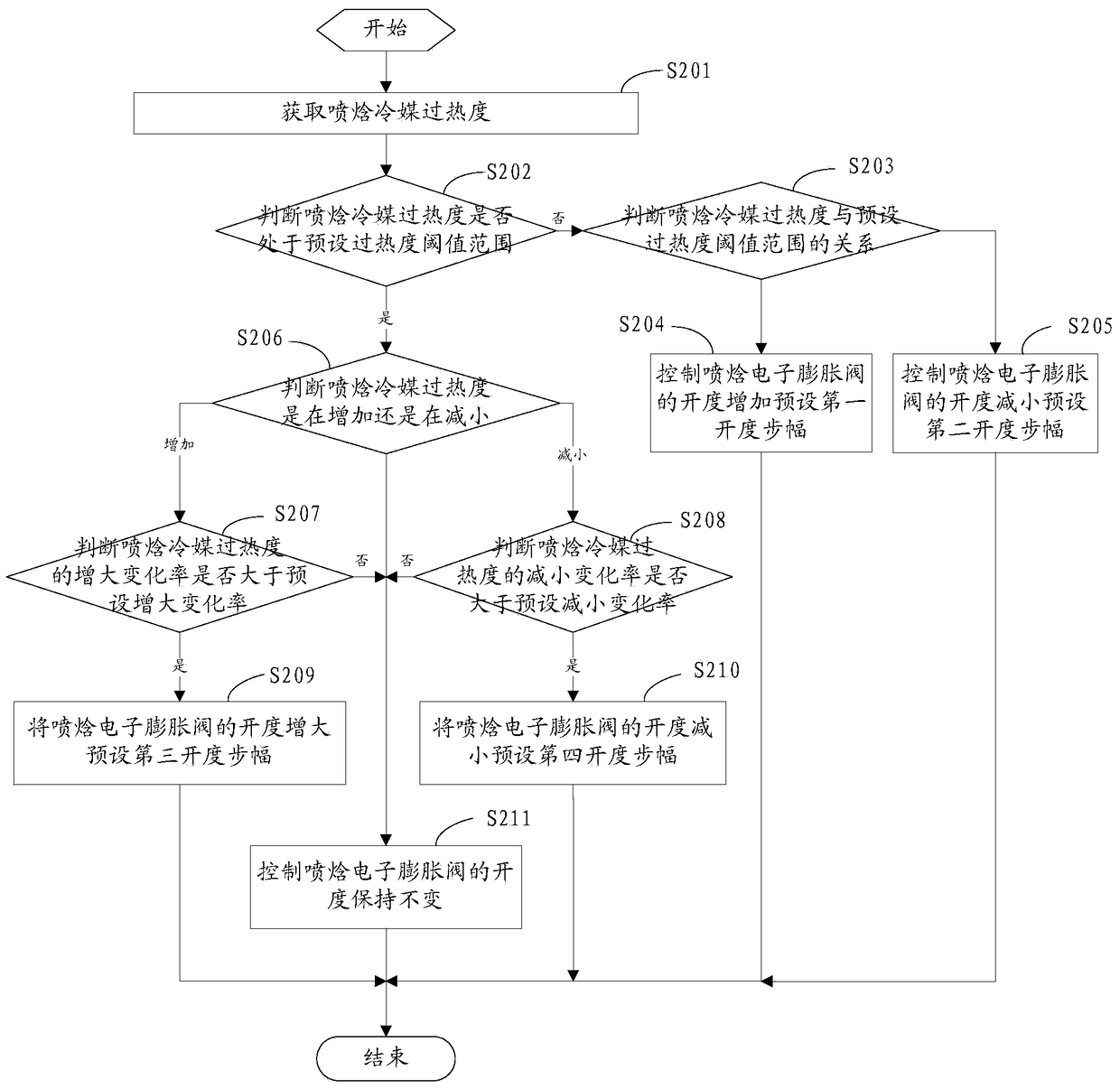
[0072] figure 2 It is a flow chart of another method for controlling the compressor discharge temperature of a low-temperature enthalpy-injected heat unit provided by an embodiment of this application.

[0073] As shown in the figure, the compressor discharge temperature control method provided in this embodiment is applied to the controller of the low-temperature enthalpy injection heat unit, and includes the following steps:

[0074] S201: Obtain the superheat of the spray enthalpy refrigerant.

[0075] Firstly, the superheat of the spray enthalpy refrigerant is obtained through the spray pressure of the refrigerant spray port and the actual temperature.

[0076] S202: Determine whether the superheat of the injection enthalpy refrigerant is within a preset superheat threshold range.

[0077] The preset superheat threshold range is a preset superheat range, and the specific value range is selected according to actual measurement and empirical formulas. Judging whether it is within th...

Embodiment 3

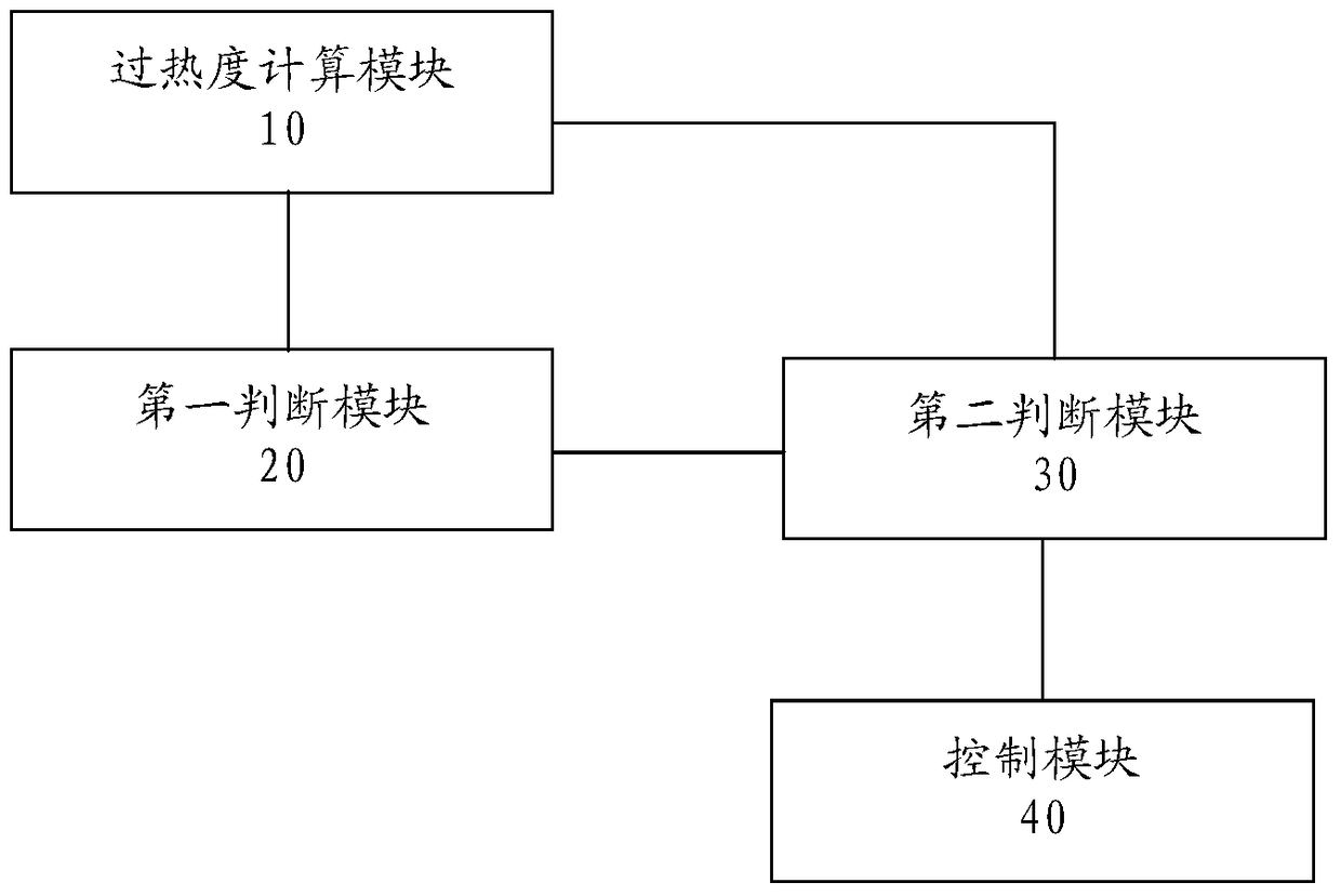
[0098] image 3 This is a schematic diagram of a compressor exhaust temperature control system of a low-temperature enthalpy-intensified heat unit provided by another embodiment of this application.

[0099] Such as image 3 As shown, the compressor discharge temperature control system provided in this embodiment includes a superheat calculation module 10, a first judgment module 20, a second judgment module 30, and a control module 40.

[0100] The superheat degree calculation module 10 is used to calculate the spray pressure and actual temperature of the refrigerant spray port to obtain the spray enthalpy refrigerant superheat degree.

[0101] The first judging module 20 is used to judge whether the superheat of the injection enthalpy refrigerant is within a preset superheat threshold range.

[0102] The preset superheat threshold range is a preset superheat range, and the specific value range is selected according to actual measurement and empirical formulas. Judging whether it is ...


PUM


Abstract

The invention discloses an exhaust gas temperature control method and system of a compressor of a low-temperature enthalpy spraying intense heating unit. According to the method and system, firstly, the enthalpy spraying coolant superheat degree of the unit is acquired; secondly, the enthalpy spraying coolant superheat degree is compared with a preset superheat degree threshold range; if the enthalpy spraying coolant superheat degree is higher than the upper-limit value of the preset superheat degree threshold range, a first preset opening degree stride is added to the opening degree of a enthalpy spraying electronic expansion valve; if the enthalpy spraying coolant superheat degree is lower than the lower-limit value of the preset superheat degree threshold range, the opening degree of the enthalpy spraying electronic expansion valve is decreased by a second preset opening degree stride; by means of the method, the enthalpy spraying coolant superheat degree can be effectively controlled within the preset superheat degree threshold range. Since the enthalpy spraying coolant superheat degree is directly related to the exhaust gas temperature of the compressor, the stability of the exhaust gas temperature of the compressor of the low-temperature enthalpy spraying intense heating unit can be effectively controlled through the method and system; consequently, potential safety hazards caused when the exhaust gas temperature of the compressor exceeds a safety fluctuation range can be effectively avoided by means of the method and system.

Description

Technical field [0001] This application relates to the field of refrigeration technology, and more specifically, to a method and system for controlling the compressor discharge temperature of a low-temperature enthalpy injection heat unit. Background technique [0002] The low-temperature enthalpy-intensified heat unit generally adopts the method of injecting refrigerant into the scroll compression cavity of the compressor to improve the heating capacity of the unit under ultra-low ambient temperature, but the unit adopting this method often has compressor discharge. The air temperature fluctuates greatly, sometimes even beyond the safe fluctuation range, which brings hidden dangers to the safe operation of the unit. Summary of the invention [0003] In view of this, the present application provides a method and system for controlling the compressor discharge temperature of a low-temperature enthalpy injection heat unit, which is used to control the compressor discharge temperatur...

Claims


Application Information

Patent Timeline
Patent Type & Authority Patents(China)
IPC IPC(8): F25B49/02
Inventor 林海东吴呈松郑伟平张恩泉魏峰
Owner GREE ELECTRIC APPLIANCES INC
Learn More