
Vapor Compression Refrigeration Cycle Expansion Work Recovery System

A compression refrigeration and recovery system technology, applied in the direction of refrigerators, compressors, refrigeration and liquefaction, etc., can solve the problems of rising exhaust temperature, limitation of temperature difference between cold and heat sources, and increase of compressor pressure ratio

Active Publication Date: 2016-06-01
TIANJIN UNIV
View PDF5 Cites 0 Cited by
  • Summary
  • Abstract
  • Description
  • Claims
  • Application Information

AI Technical Summary

Problems solved by technology

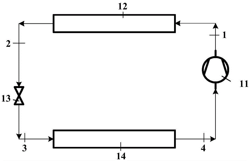
The problem with this device is that it is limited by the compressor, and the traditional single-stage vapor compression refrigeration cycle has certain limitations on the temperature difference between the cold and heat sources.
The traditional vapor compression cycle is generally suitable for working conditions where the temperature rise of the cycle is less than 70°C. This is because as the temperature rise of the cycle increases, the compressor pressure ratio will increase accordingly, which will lead to a decrease in compressor efficiency and an increase in power consumption. , the exhaust temperature rises, and eventually causes the cycle performance to deteriorate

Method used


Image

  • Vapor Compression Refrigeration Cycle Expansion Work Recovery System
  • Vapor Compression Refrigeration Cycle Expansion Work Recovery System
  • Vapor Compression Refrigeration Cycle Expansion Work Recovery System

Examples


Embodiment

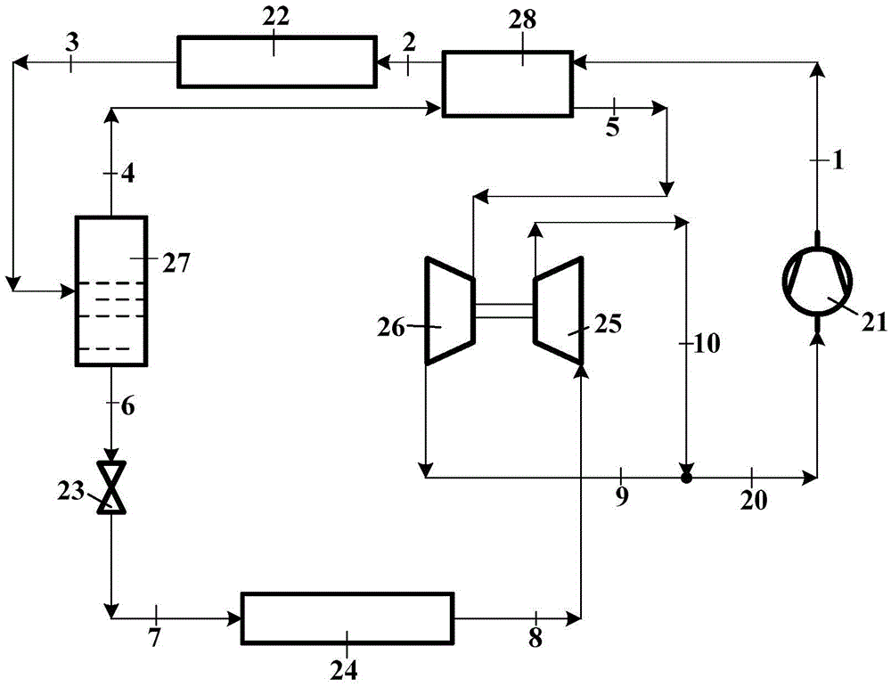
[0058] Figure 5 It is the temperature-entropy diagram of the vapor compression refrigeration cycle using R134a as the working medium, the state points 1, 2, 3, 4, 5, 6, 7, 8, 9, 10, 20, 1 in the figure ', 2', 9', 10' and 20' (1', 2', 9', 10' and 20' are the import and export states of the isentropic compression or expansion process) and image 3 Consistent with that shown. Taking the heat pump system as an example, the parameters of each state point including temperature, pressure and enthalpy are listed in Table 2. In the temperature-entropy diagram, the dotted line represents the isentropic expansion and compression process.

[0059] Table 2

[0060]

[0061]

[0062] According to the literature, the isentropic efficiency of the scroll expander using 134a as the working fluid is set at 0.7. Considering that the isentropic efficiency of the compressor is significantly affected by the compression ratio, for this compressor, its isentropic efficiency is calculated as...


PUM


Abstract

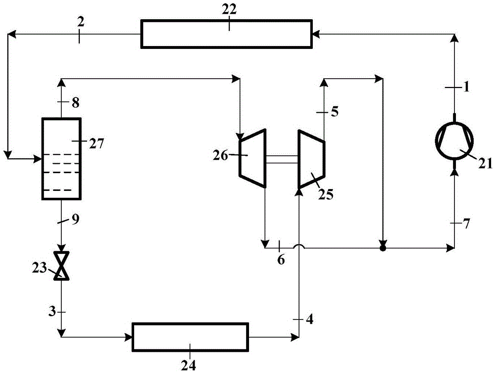
The invention discloses a vapor compression refrigeration cycle expansion work recovery system. The system comprises a main compressor (i), a condenser (ii), a gas and liquid separator (iii), a gas expander (iv), an expansion valve (v), an evaporator (vi) and an auxiliary compressor (vii), wherein the condenser (ii) is connected with the main compressor (i) and cools gaseous working mediums from the main compressor into a gas and liquid two-phase mixture; the gas and liquid separator (iii) is connected with the condenser and performs phase separation on the gas and liquid two-phase mixture from the condenser; the gas expander (iv) is connected with a gas phase working medium outlet of the gas and liquid separator; the expansion valve (v) is connected with a liquid phase working medium outlet of the gas and liquid separator; the evaporator (vi) is connected with the expansion valve; the auxiliary compressor (vii) is connected with the evaporator; a gaseous working medium outlet of the gas expander and a gaseous working medium outlet of the auxiliary compressor are jointly communicated with a gaseous working medium inlet of the main compressor through a pipeline. Due to stage compression of the system, the compression ratio in each compression process is decreased, the efficiency of the compressors is guaranteed, and the circulation COP is improved.

Description

technical field [0001] The invention relates to an expansion work recovery system, in particular to a vapor compression refrigeration cycle expansion work recovery system. Background technique [0002] The vapor compression refrigeration cycle based on thermodynamic processes such as evaporation, compression, condensation, and throttling can realize the reverse transfer of heat from a low-temperature environment to a high-temperature environment, thereby providing stable cooling / heating loads for industrial production and daily life. In my country, the application of refrigeration and heat pump equipment based on vapor compression cycles is growing rapidly, which not only leads to a continuous increase in electricity demand, indirectly promotes the consumption of fossil fuels such as coal, but also exacerbates the seasonal unevenness of grid load, threatening The overall security of the grid. Therefore, optimizing the vapor compression refrigeration cycle has important pract...

Claims


Application Information

Patent Timeline
Patent Type & Authority Patents(China)
IPC IPC(8): F25B1/10
Inventor 赵力郑楠杨兴洋鲍军江
Owner TIANJIN UNIV
Learn More