
A rotary kiln support device and its adjustment method

An adjustment method and rotary kiln technology, applied in the fields of building materials, metallurgy, and chemical industry, can solve the problems of difficulty and cost in transportation and installation, large tire size, and high manufacturing cost, and achieve reduced width and thickness, reduced maintenance times, and reduced The effect of maintenance costs

Inactive Publication Date: 2017-06-09
SOUTHWEST UNIV
View PDF2 Cites 0 Cited by
  • Summary
  • Abstract
  • Description
  • Claims
  • Application Information

AI Technical Summary

Problems solved by technology

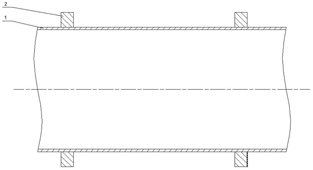
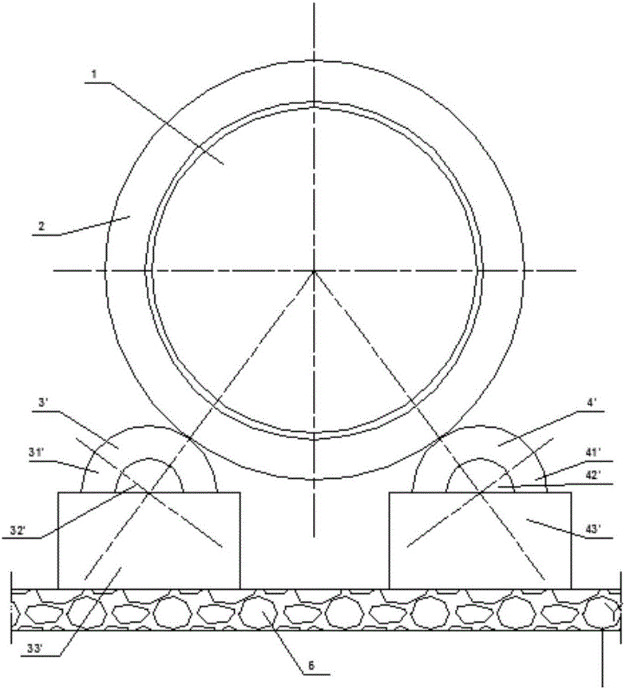
like Figure 1-2 As shown, the roasted material of the rotary kiln is placed in the cylinder of the rotary kiln, and the cylinder is supported by supporting wheels arranged on both sides of the rotary kiln cylinder. The supporting wheels transmit the supporting force to the bearing seat through the supporting wheel shaft, and then to the foundation. , the left side and the right side of the wheel belt 2 are respectively provided with a structure of a left supporting wheel 31' and a right supporting wheel 41', and the rotary kiln is roughly supported by two supporting wheels connected with the wheel belt, as in 201110292366.7 and 201410417280.6, both For this kind of structure, in recent years, the rotary kiln has been continuously developing in the direction of large-scale and gigantic, and this kind of structure has the following shortcomings: 1. The supporting force of the rotary kiln continues to increase with the increase of the rotary kiln, and each supporting wheel The direct supporting force and contact force with the tire increase accordingly, so the cross-section of the tire and supporting roller is continuously increased to ensure that it has sufficient strength to prevent the deformation of the tire, supporting roller and cylinder. Such a large rotary kiln It is very difficult to manufacture tires and support rollers. They are usually integrally cast, with high defect rates and high scrap rates, so the manufacturing cost is very high. At the same time, due to the huge size of the tires, the difficulty and cost of transportation and installation are very high. With the rotary kiln The size increases geometrically; 2. Since the supporting device bears a huge supporting force, and the supporting wheel rotates with the tire belt, failures such as wear and burning often occur, and it is necessary to replace and repair the supporting wheel shaft and bearings. The current structure , because each support is supported by two support rollers, when repairing or replacing the support rollers, the cylinder itself cannot maintain stability, resulting in on-site maintenance only partial replacement of parts, long maintenance time, high maintenance costs, and difficult quality assurance

Method used


Image

  • A rotary kiln support device and its adjustment method
  • A rotary kiln support device and its adjustment method
  • A rotary kiln support device and its adjustment method

Examples


Embodiment Construction

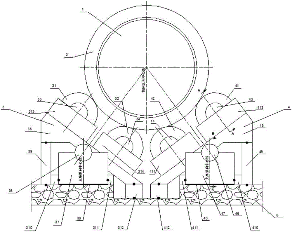
[0017] The following will be combined with Figure 1-3 The technical solution of the present invention is described in detail.

[0018] The present invention provides a rotary kiln support with a support structure of multiple supporting rollers, which includes: two left supporting rollers, namely the first supporting roller 31 and the second supporting roller 32; two right supporting rollers, namely the third supporting roller Supporting roller 41, fourth supporting roller 42, first hydraulic cylinder 39, third hydraulic cylinder 312, fifth hydraulic cylinder 310, seventh hydraulic cylinder 311; second hydraulic cylinder 49, fourth hydraulic cylinder 412, sixth hydraulic cylinder 410, the eighth hydraulic cylinder 411; the first supporting wheel shaft 33, the second supporting wheel shaft 34, the third supporting wheel shaft 43, the fourth supporting wheel shaft 44,

[0019] Such as image 3 As shown, four supporting rollers are set at each support position in this way. Duri...


PUM


Abstract

A rotary kiln support with a multi-supporting roller support structure, characterized in that it includes a first supporting roller (31), a second supporting roller (32), a first hydraulic cylinder (39), and a third hydraulic cylinder on the left side (312), the fifth hydraulic cylinder (310), the seventh hydraulic cylinder (311), the first supporting roller shaft (33), the second supporting roller shaft (34); the third supporting roller (41) on the right side, the fourth supporting roller Supporting roller (42), second hydraulic cylinder (49), fourth hydraulic cylinder (412), sixth hydraulic cylinder (410), eighth hydraulic cylinder (411), third supporting roller shaft (43), fourth supporting roller shaft (44). The rotary kiln support of the present invention can significantly reduce the width and thickness of the tire belt of the rotary kiln, reduce the difficulty and cost of manufacturing, transportation and installation; in addition, the support force is reduced, so that the contact stress between the tire belt and the supporting roller is reduced, and the contact stress The lowering will reduce the wear of the tire belt and the supporting roller, and prolong the service life of the supporting roller and the tire belt.

Description

technical field [0001] The invention relates to the fields of chemical industry, metallurgy, building materials and the like, in particular to a rotary kiln support device and an adjustment method thereof. [0002] technical background [0003] Rotary kiln is a core industrial production process equipment for roasting high-temperature materials, and it is widely used in industrial production. Such as Figure 1-2 As shown, the roasted material of the rotary kiln is placed in the cylinder of the rotary kiln, and the cylinder is supported by supporting wheels arranged on both sides of the rotary kiln cylinder. The supporting wheels transmit the supporting force to the bearing seat through the supporting wheel shaft, and then to the foundation. , the left side and the right side of the wheel belt 2 are respectively provided with a structure of a left supporting wheel 31' and a right supporting wheel 41', and the rotary kiln is roughly supported by two supporting wheels connected ...

Claims


Application Information

Patent Timeline
Patent Type & Authority Patents(China)
IPC IPC(8): F27B7/22
Inventor 姚凌云李丽
Owner SOUTHWEST UNIV
Learn More