Three-dimensional Shape Measurement Apparatus

A measuring device and technology of three-dimensional shape, applied in the field of three-dimensional shape measuring device, can solve the problems of weak rotation rigidity, measurement error, difficult to realize measurement, etc.

Active Publication Date: 2015-12-23
PANASONIC INTELLECTUAL PROPERTY MANAGEMENT CO LTD
View PDF4 Cites 1 Cited by
  • Summary
  • Abstract
  • Description
  • Claims
  • Application Information

AI Technical Summary

Problems solved by technology

Then, as a result, the rotational rigidity of the Z-axis driving shaft 220 becomes weak, and a measurement error ΔX is likely to occur at the front end of the detection part at a high inclination angle (30 degrees to 70 degrees).
In t

Method used


Image

  • Three-dimensional Shape Measurement Apparatus
  • Three-dimensional Shape Measurement Apparatus
  • Three-dimensional Shape Measurement Apparatus

Examples


Embodiment Construction

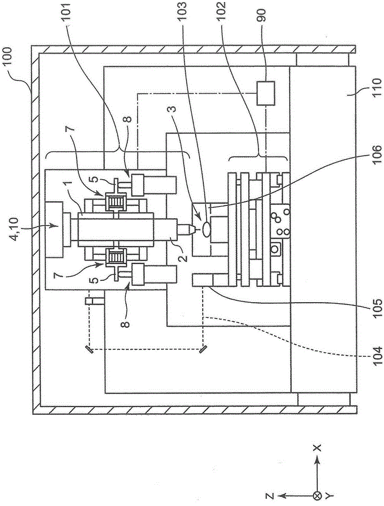
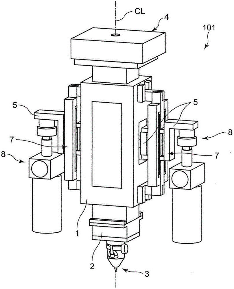
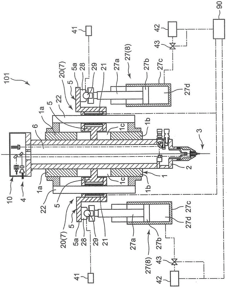
[0050] Hereinafter, the three-dimensional shape measurement device 100 according to the embodiment of the present invention will be described in detail with reference to the drawings. figure 1 The overall structure of the three-dimensional shape measuring device 100 is shown.

[0051] The three-dimensional shape measuring apparatus 100 includes an XY table 102 , a Z-axis table section 101 , and a control section 90 . The XY table 102 is disposed on the platform 110 so as to be movable in the XY axis direction, and the XY table 102 is used to mount and hold the measurement object 103 so that the measurement object 103 can move in the XY axis direction. The Z-axis table part 101 is supported by the platform 110 so as to be able to move along the Z-axis direction, that is, the vertical direction (vertical direction), and supports the detection part 3 which contacts the measurement surface of the measurement object 103 at the lower end, so that the detection part 3 can Moving up...


PUM


Abstract

A three-dimensional shape measurement apparatus includes an air-slider outer frame, an air-slider hollow shaft movable in an axial direction in the outer frame, two support arms, two driving portions, and two support portions. The air-slider hollow shaft is provided with a through-hole to form an optical path connecting a focus optical system on an upper end and a probe portion on a lower end. The support arms protrude from both sides of the hollow shaft in a lateral direction, at vertical positions corresponding to an integration gravity center of the focus optical system, the probe portion, and the hollow shaft, symmetrically with respect to a central axis of the hollow shaft. The driving portions are located at positions in the vicinity of the hollow shaft in the support arms, symmetrically with respect to the central axis of the hollow shaft. The driving portions drive the hollow shaft in the axial direction with respect to the outer frame. In the support arms, the support portions are disposed further away from the hollow shaft than the driving portions, symmetrically with respect to the central axis of the hollow shaft, and support the support arms movably in the lateral direction.

Description

technical field [0001] The present invention relates to a three-dimensional shape measurement device for scanning and measuring an arbitrary three-dimensional shape measuring object (for example, an aspheric lens used in a smartphone, etc.) with high precision. Background technique [0002] like Figure 23 As shown, the following device is disclosed in Non-Patent Document 1. The detection part 201 is arranged at the lower end of the Z-axis driving shaft 220 of the Z-axis driving device 200 with gravity compensation in the Z-axis direction, and the detection part 201 is placed on the XY The three-dimensional shape of the measurement object 203 on the stage 202 is measured. [0003] In this device, the Z-axis driving shaft 220 of the Z-axis driving device 200 is configured to be evacuated by the vacuum cylinder 204 on the upper part of the Z-axis driving device, thereby minimizing the self-weight of the Z-axis driving shaft 220 for compensation. The Z-axis drive shaft 220 is ...

Claims


Application Information

Patent Timeline
IPC IPC(8): G01B11/24
CPCG01B5/0011G01B5/0002G01B11/005G01B11/007
Inventor 荒木贵久舟桥隆宪川西努竹内博之
Owner PANASONIC INTELLECTUAL PROPERTY MANAGEMENT CO LTD
Why Eureka
Try Eureka