[0021] The following will clearly and completely describe the technical solutions in the embodiments of the present invention with reference to the accompanying drawings in the embodiments of the present invention. Obviously, the described embodiments are only some, not all, embodiments of the present invention. Based on the embodiments of the present invention, all other embodiments obtained by persons of ordinary skill in the art without creative efforts fall within the protection scope of the present invention.
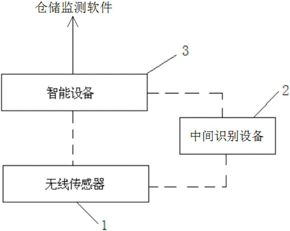
[0022] A method for synchronizing location information of wireless sensors for monitoring storage parameters, including establishing or using software for monitoring storage parameters and arranging wireless sensors 1 in areas to be monitored. The storage parameter monitoring software is developed by itself or calls software developed by others through API. The wireless sensor 1 is a variety of wireless sensors 1 used to obtain storage parameters, such as wireless temperature and humidity sensors, wireless oxygen concentration sensors, wireless mildew sensors, wireless carbon dioxide sensors, etc., such as wireless temperature and humidity sensors used in the field of raw tobacco storage environmental parameter monitoring sensor, wireless oxygen concentration sensor, etc. The wireless sensor 1 also refers to devices in the form of temperature probes, humidity probes, and temperature and humidity probes using wireless transmission technology. like figure 1 As shown, the identification information of the wireless sensor 1 is acquired by a smart device 3 directly or indirectly through the intermediate identification device 2 , that is, the smart device 3 acquires the identification information carried in the information carrier of the wireless sensor 1 .
[0023] After the identification information carried by the information carrier of the wireless sensor 1 is acquired by the smart device 3, the smart device 3 performs data interaction with the storage parameter monitoring software and binds the wireless sensor 1 with its location information.
[0024] After the smart device 3 obtains the identification information of the wireless sensor 1, there are three ways to bind the location:
[0025] A: By operating the user interface of the application program in the smart device 3, bind the interactive control representing the location information of the wireless sensor 1 on the user interface with the sensor 1. The interactive control can be a button, an input box, a drop-down list, a radio box, checkbox etc.
[0026] B: Binding is performed by operating physical keys, buttons, touch pads, sensing areas, etc. that represent the placement position of the wireless sensor 1 in the intermediate identification device 2 .
[0027] C. Binding is performed by touching the wireless identification area, wireless induction area, etc. in the intermediate identification device 2 that represent the placement position of the wireless sensor 1 .
[0028] The smart device 3 is one of smart phones, tablet computers, PDAs, tablet computers and other devices; the intermediate identification device 2 is a card reader, an induction plate, a code scanner, a code scanner, a belt One of the identification devices such as RFID or Bluetooth-enabled 802.15.4 routers, custom-developed identifiers, etc. like figure 2As shown, the wireless sensor 1 has built-in RF transceiver control unit 11 , RFID/NFC unit 13 , RTC chip 10 , power supply unit 14 , sensing element 12 and antenna 15 . RF transceiver control unit 11 is connected with RFID/NFC unit 13 and RTC chip 10 respectively, and RF transceiver control unit 11 carries out data transmission based on IEEE802.15.4 standard, and RTC chip 10 is connected with RF transceiver control unit 11, can carry out network time synchronization, can An interrupt is output to the RF transceiver control unit 11 . The RF transceiver control unit 11 is connected to the sensing element 12 to acquire data collected by the sensing element 12 . The RF transceiving control unit 11 is connected to the antenna 15 for wireless transceiving. The wireless sensor 1 is provided with one or more information carriers in two-dimensional code, bar code and RFID/NFC label. The RFID/NFC unit 13 is composed of an RFID/NFC read-write chip and peripheral circuits. The RFID/NFC unit 13 can be directly Communicate with smart devices 3 or intermediate identification devices 2 with RFID/NFC communication functions, and the communication content includes the number (ID), type, MAC address, short address, extended address, placement location, alias, key, Operating instructions, historical data, time and other information.
[0029] The RF components in the RFID/NFC unit 13 and the RF transceiver control unit 11 can be single or two. The RF transceiver control unit 11 performs control and calculation and is responsible for the amplification and transceiver of the radio frequency. It can adopt a structure composed of a radio frequency transceiver system-on-chip with an MCU and an amplified chip, or a structure composed of an MCU, a radio frequency transceiver chip, and a radio frequency amplifier chip. structure. The RF transceiver control unit 11 adopts wireless communication technology conforming to the IEEE802.15.4 standard, can perform network operation with other compatible devices, and has an ultra-low power consumption sleep function. When the device does not need to send and receive data externally, it can sleep. Networking between node devices forms a large wireless sensor network.
[0030] The RF transceiver control unit 11 based on 802.15.4, and the RFID/NFC communication function can be shielded or disabled by setting (modifying) at the software or hardware level, so that the sensor only works in the 802.15.4 communication mode, or only in the RFID/NFC communication mode.
[0031] The power supply unit 14 is used to provide power for each chip, unit or component, and is composed of a power conversion chip, a charging chip and peripheral circuits/components. The wireless sensor 1 is also provided with a transducer assembly connected to the power supply unit 14, the transducer assembly is a device that converts other forms of energy into electric energy, and it can be a dry cell, various rechargeable batteries (such as a rechargeable nickel-metal hydride battery , rechargeable nickel-cadmium batteries, rechargeable lithium-ion batteries, rechargeable lithium polymer batteries, etc.), fuel cells, photoelectric solar panels, and wireless energy harvesters. The charging chip can be configured or not configured according to the type of the transducer device of the device.
[0032] The sensing element 12 is connected with the RF transceiver control unit 11. The data collected by the sensing element 12 can be actively or passively transmitted wirelessly through the RF transceiver control unit 11 and the RFID/NFC unit 13. The sensing element is a temperature sensing element, a humidity sensor Sensing element, temperature and humidity integrated sensing element, CO 2 Concentration sensing element, O 2 One or more of concentration sensing elements, gas sensing elements, pressure sensing elements, light intensity sensing elements, acceleration sensing elements, and displacement sensing elements; the above-mentioned various sensing elements are in the form of a single core element, One of chip form or module package form. According to the different sensing elements, using this node device as the core can form wireless temperature sensors, wireless humidity sensors, wireless temperature and humidity integrated sensors, wireless pressure sensors, wireless C0 2 sensor, wireless 2 Sensors, wireless gas sensors, wireless light intensity sensors, wireless acceleration sensors, wireless displacement sensors, 802.15.4 standard RFID/NFC readers with sleep and networking functions, 802.15.4 routers, etc.
[0033] The smart device 3 and the wireless sensor 1 can use wireless data transmission technology, automatic identification technology, manual selection, keyboard input, handwriting input and other ways to transmit identification information. The wireless data transmission technology can be RFID, NFC, Bluetooth, infrared data transmission, home radio frequency, wireless local area network, WIFI and WLAN and other communication technologies. Of course, wired transmission technology can also be used for data transmission, such as through USB, Lighting, serial port, parallel port, LAN and other technologies. Automatic recognition technology can be QR two-dimensional code recognition, bar code recognition, OCR optical character recognition and other technologies.
[0034] For the binding of the above-mentioned mode A: in this mode, the smart device 3 is a smart phone, a PDA or a tablet computer, and its operating system can be IOS, ANDROID, WINDOWSPHONE, WINDOWSMOBILE, LINUX, etc. By installing a dedicated APP (application software) on the smart device, the operation interface in the APP (application software) is provided with interactive controls representing the position information of the wireless sensor 1, such as buttons, text boxes, drop-down lists, radio boxes, check boxes Wait. After the user operates the interactive control corresponding to the corresponding location information, and then obtains the identification information of the wireless sensor 1 by scanning the QR code or barcode on the wireless sensor 1, or reading the RFID/NFC tag of the wireless sensor 1, and then the APP ( application software) to complete the binding of the wireless sensor 1 and the location information. In the case of an intermediate identification device 2, for example, the intermediate identification device 2 is the upper-level routing device of the wireless sensor 1, and the smart device APP (application software) obtains the intermediate device through Bluetooth, RFID or the data transmission method described above. The identification information of the wireless sensor 1 or the sensor list 1, and then through the above-mentioned various interactive controls in the APP (application software), select the corresponding location for binding, or operate the corresponding APP (application software) that characterizes the location Control, and then select the corresponding wireless sensor 1 entry from the wireless sensor 1 list to realize the binding.
[0035] For mode B or mode C, the intermediate identification device 2 can be an operation panel, manipulator, or sensor customized according to the application field of storage parameter monitoring, which is provided with keys, buttons, sensors, etc. that can be operated to characterize the placement position of the sensor. area, identification area, etc., after this type of intermediate identification device 2 is connected to the smart device 3 through the above-mentioned various connection methods, and then obtains the identification information of the wireless sensor 1 from the above-mentioned various information carriers through the above-mentioned various ways, the user Operate the keys, buttons and other parts in the intermediate recognition device 2, and the APP (application software) installed on the smart device 3 will automatically perform the associated binding operation.
[0036] The storage parameter monitoring software can be a self-developed application program based on PC or server. This type of self-developed application program is developed using industrial configuration software or traditional software development tools; The open IoT platform; or through API access to software systems developed by users or others, such as ERP, warehouse management systems, etc. The storage parameter monitoring software structure is software with B/S structure or C/S structure.
[0037] Using this method, a series of brand-new storage parameter detection solutions can be constructed. For example, using the above-mentioned wireless temperature sensor, wireless humidity sensor, wireless temperature and humidity integrated sensor, wireless 0 2 Concentration sensor, wireless CO 2 Concentration sensors and corresponding storage monitoring software can be built for storage temperature, humidity, oxygen concentration, CO 2 Wireless monitoring system for concentration monitoring.
[0038] For example, using the above-mentioned wireless temperature sensor, wireless humidity sensor, wireless temperature and humidity integrated sensor, and wireless acceleration sensor can build a wireless monitoring system for logistics and transportation monitoring, and monitor the environment of pharmacies, home environments, factory buildings, office and commercial environments, etc. Parameter wireless monitoring system.
[0039] For example, using the above-mentioned wireless temperature sensor, wireless humidity sensor, wireless temperature and humidity integrated sensor, wireless C0 2 Sensor sensors and wireless light intensity sensors can be used to build a wireless monitoring system for monitoring flue-cured tobacco seedling greenhouses.
[0040] For example, a wireless monitoring system for animal body temperature and exercise monitoring can be constructed by using the above-mentioned wireless temperature sensor and wireless acceleration sensor.
[0041] For example, a wireless monitoring system for human body temperature and exercise monitoring can be constructed by using the above-mentioned wireless temperature sensor and wireless acceleration sensor.
[0042] The above descriptions are only preferred embodiments of the present invention, and are not intended to limit the present invention. Any modifications, equivalent replacements, improvements, etc. made within the spirit and principles of the present invention shall be included in the scope of the present invention. within the scope of protection.