Batch steel pipe pressure test device

A pressure test, steel pipe technology, applied in the direction of applying stable tension/pressure to test the strength of materials, etc., can solve the problems of high construction cost, waste of human resources and material resources, low construction efficiency, etc., to avoid temporary welding and reduce main materials. The effect of high consumption and pressure test efficiency

Active Publication Date: 2017-12-12
广西建工集团第二安装建设有限公司
View PDF7 Cites 0 Cited by
  • Summary
  • Abstract
  • Description
  • Claims
  • Application Information

AI Technical Summary

Problems solved by technology

The shortcomings of conventional pressure testing mainly include: (1) complex process and low construction efficiency, the joints need to be welded when the pipeline is connected, and the joints need to be cut after the pressure test; (2) the construction cost is high, the waste of resources is serious, and the pipeline The welding and cutting of the joints will cause a lot of waste of human resources and material resources, which is not conducive to the purchase of heat exchange tube base materials with customized lengths. The repetition rate of individual pressure test operations for a single pipe is high, labor intensity is high, and operating costs are high.

Method used


Image

  • Batch steel pipe pressure test device
  • Batch steel pipe pressure test device
  • Batch steel pipe pressure test device

Examples


Embodiment Construction

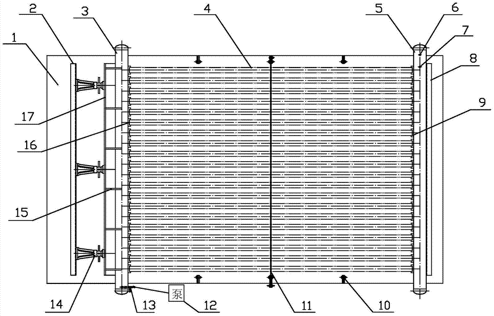
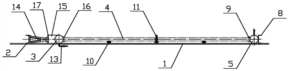
[0026] like Figure 1 to Figure 11 As shown, the batch steel pipe pressure test device of the present invention includes a pressure test bench 1 , a pressure test manifold, a jacking clamping device, a pressure test tube positioning device, and a pressure test pump 12 .

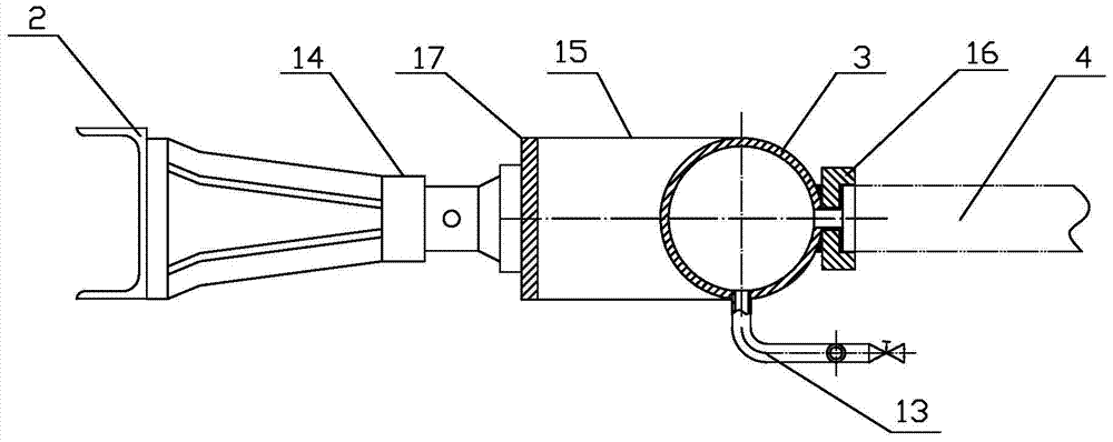
[0027] The pressure test manifold includes manifold I3 and manifold II5 respectively arranged on both sides of the pressure test platform 1 and oppositely arranged, the pressure test platform 1 is a base steel plate, and the main bodies of the manifold I3 and manifold II5 are seamless steel pipes. Both ends are welded and sealed with oval heads. On the inner side of the confluence pipe I3, there is a row of nozzles I20 that penetrate the wall of the confluence pipe I3 ​​and are arranged equidistantly. The positions correspond to each other. The nozzle I20 and the nozzle II are formed by drilling, and the nozzle I20 and the nozzle II are round holes of Φ15mm. A pressure test socket I16 connected to the manif...


PUM


Abstract

The batch steel pipe pressure test device of the present invention relates to a steel pipe pressure test device, which includes a pressure test table, a pressure test manifold, a jacking clamping device, a pressure test tube positioning device, and a pressure test pump. On both sides of the pressure test table and opposite to the confluence pipe I II, there is a relatively set pressure test pipe seat on the inner side of the confluence pipe I II, and the jacking and clamping device includes a fixed baffle I II, a jack, a jacking steel plate, and a welded half-ring plate , the fixed baffle Ⅰ is welded on the pressure test bench and located outside the manifold Ⅰ, the jack, the jacking steel plate, and the welded half-ring plate are sequentially arranged between the fixed baffle Ⅰ and the manifold Ⅰ from outside to inside, and the fixed baffle II Set on the outside of the confluence pipe II, the jack transmits the thrust to the confluence pipe I through the jacking steel plate and the welded half-ring plate, so that the pressure test steel pipe is clamped and sealed in the pressure test pipe seat between the confluence pipe II and passed through the pressure test pipe The positioning device locates the middle part of the steel pipe. The invention has the advantages of high pressure testing speed, simple operation, low operation cost and the like.

Description

technical field [0001] The invention relates to a steel pipe pressure test device, in particular to a device capable of performing steel pipe pressure test in batches. Background technique [0002] Conventional size preheaters, heat exchangers and other equipment contain hundreds of heat exchange tubes, and the heat exchange tubes need to be hydrostatically tested before installation. The conventional heat exchange tube pressure test method is to weld multiple heat exchange tubes in series to form a long pipe, and weld blocking plates at both ends of the long pipe for pressure test or a single pipe for separate pressure test. The shortcomings of conventional pressure testing mainly include: (1) complex process and low construction efficiency, the joints need to be welded when the pipeline is connected, and the joints need to be cut after the pressure test; (2) the construction cost is high, the waste of resources is serious, and the pipeline The welding and cutting of the j...

Claims


Application Information

Patent Timeline
Patent Type & Authority Patents(China)
IPC IPC(8): G01N3/12
Inventor 何际乐覃幼辙姜斌林秋蕙张瑞薪
Owner 广西建工集团第二安装建设有限公司
Why Eureka
Try Eureka