Detector signal readout channel multiplexing method

A signal readout and readout channel technology, applied in the field of nuclear detection technology and nuclear medicine imaging, can solve the problems of high dynamic range of the back-end readout circuit, large dynamic range of output signals, and excessive input and output signals. The effect of the requirement on the time resolution of the terminal readout circuit

Active Publication Date: 2015-12-23
RAYCAN TECH CO LTD SU ZHOU
View PDF33 Cites 11 Cited by
  • Summary
  • Abstract
  • Description
  • Claims
  • Application Information

AI Technical Summary

Problems solved by technology

However, when the resistance network is used, due to the different signal access points, the equivalent resistance of the resistance network for different detectors is also different, which eventually causes a large difference in the output signal amplitude of different detectors, requiring the back-end readout The circuit has a high dynamic range
However, the current conventional processing circuit has a limited dynamic range, and the signal-to-noise ratio is poor when the input signal is small, and there will be saturation problems when the input and output signals are too large.
[0005] Therefore, in view of the above technical problems, it is necessary to provide a channel multiplexing method for detector signal readout with an improved structure, to overcome the above defects, and effectively solve the problem that the dynamic range of the output signal after the multiplexing of the detector channels is too large

Method used


Image

  • Detector signal readout channel multiplexing method
  • Detector signal readout channel multiplexing method
  • Detector signal readout channel multiplexing method

Examples


Embodiment Construction

[0054] The invention discloses a channel multiplexing method for detector signal readout, which can reduce the use of electronic channels, effectively reduce the requirement on the dynamic range of the back-end readout circuit, and reduce the time of the back-end readout circuit resolution requirements.

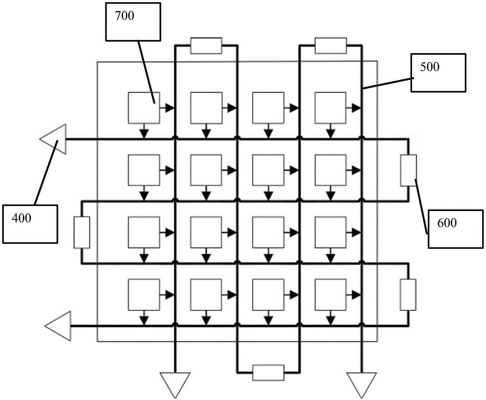
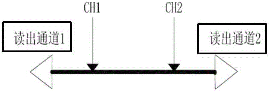
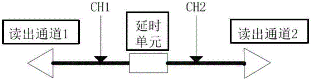
[0055] Such as figure 1 As shown, when a pulse signal is introduced into a transmission line with readout circuits at both ends, the signal will propagate to both sides of the access point respectively. Such as figure 2 As shown, at this time, if a delay unit is added to the transmission line, since the propagation speed of the signal on the transmission line is much greater than the speed passing through the delay unit, the time difference between the signal reaching the readout channel at both ends will be determined by the delay unit on the transmission line . Further, such as image 3 As shown, several delay units are introduced into a transmission line, because the ...


PUM


Abstract

A detector signal readout channel multiplexing method comprises the steps as follows: grouping L detectors to form a first source signal and a second source signal; respectively introducing L detector signals into a first signal transmission line including two readout channels A and B and a second signal transmission line including two readout channels C and D, and simultaneously introducing first signal delay units and second signal delay units to the first signal transmission line and the second signal transmission line; and marking source detectors for signal forming according to the four readout channels A, B, C and D and obtaining final pulse information. According to the invention, only four readout channels are needed for one flat plane detector, and the problem that the number of one-to-one readout channels is too large is solved effectively. Time division multiplexing design of the transmission lines ensures that the waveform of signals output by detectors in different positions is similar to the mode of one-to-one readout, and the requirement on the dynamic range of a backend readout circuit is lowered. Moreover, the delay units are added, which greatly lowers the requirement on the time resolution of the backend readout circuit.

Description

technical field [0001] The invention relates to the fields of nuclear detection technology and nuclear medical imaging technology, in particular to a channel multiplexing method for detector signal readout. Background technique [0002] In a clinical positron emission tomography (Positron Emission Tomography, hereinafter referred to as PET) equipment, the number of detectors is as many as 30,000. Direct readout of the electrical signal produced by each detector requires 30,000 channels of electronic processing. The large number of electronic channels makes the entire PET electronic system expensive and difficult to implement. [0003] In response to the above situation, researchers focused on the research and development of channel multiplexing technology for detector signal readout. The current mainstream readout channel multiplexing method is to weight the output signal of the detector signal by row and column with a resistor network and then read it out. [0004] The u...

Claims


Application Information

Patent Timeline
Patent Type & Authority Applications(China)
IPC IPC(8): G01T1/16
CPCG01T1/17G01T1/2985G01T1/161A61B6/037G01T1/1642G01T1/1647G01T1/1648H04J3/0617
Inventor 谢庆国华越轩温惠华奚道明
Owner RAYCAN TECH CO LTD SU ZHOU
Why Eureka
Try Eureka