Supercharge Your Innovation With Domain-Expert AI Agents!

Equipment for pressing rotor shaft in rotor ring of motor

A rotor shaft and equipment technology, which is applied to welding equipment, metal processing equipment, manufacturing stator/rotor body, etc., can solve the problems of less functions and waste of manpower, and achieve the effect of high automation and manpower saving

Active Publication Date: 2015-12-23
青岛海德泰克电机有限公司
View PDF11 Cites 13 Cited by
  • Summary
  • Abstract
  • Description
  • Claims
  • Application Information

AI Technical Summary

Problems solved by technology

[0008] The present invention aims at the above shortcomings, and is based on solving the problem that the existing motor rotating ring pressing rotor shaft equipment has few functions and wastes manpower.

Method used


Image

  • Equipment for pressing rotor shaft in rotor ring of motor
  • Equipment for pressing rotor shaft in rotor ring of motor
  • Equipment for pressing rotor shaft in rotor ring of motor

Examples


Embodiment 1

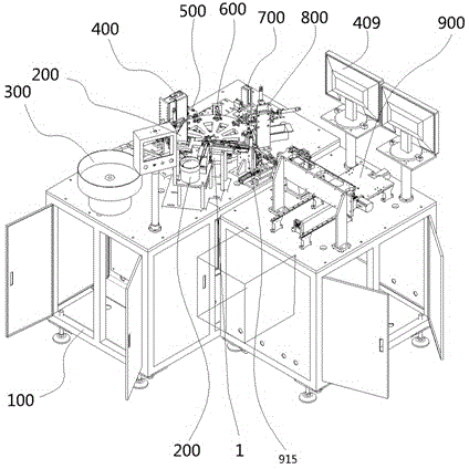
[0034]The equipment for rotating the motor to press the rotor shaft includes a workbench 100 on which the turntable device 1 is installed. The workbench 100 is sequentially installed with a rotor shaft supply device 200 along the side, a circle supply mechanism 300, a CCD camera mechanism 400, a pressure welding Mechanism 500, slag removal mechanism 600, defective product removal mechanism 800 and unloading mechanism 900. Described turntable device 1 comprises disc 15, and support 14 is installed below disc 15, and the motor one 13 that drives disc 15 rotation is installed on described support 14 side; Motor one 13 drives disc 15 to rotate through belt 12 transmission, Motor one 13 is a PLC controlled motor, and a workpiece placement groove 16 is installed on the disc 15 . The workpiece puts groove 16 side also to be equipped with stopper 11, and the main function of stopper 11 is to be used for blocking workpiece.

[0035] The rotor shaft supply device 200 includes a base pl...


PUM


Abstract

The invention provides equipment for pressing a rotor shaft in a rotor ring of a motor. The equipment comprises a workbench, wherein a turntable device is installed on the workbench. The equipment is characterized in that a rotor shaft feed device, a rotor ring feed mechanism, a CCD (charged-coupled device) camera mechanism, a pressure welding mechanism, a deslagging mechanism, a defective product removal mechanism and an unloading mechanism are installed along the edge of the workbench in order. Compared with the prior art, the equipment has the advantages that the equipment can automatically complete loading, welding, polishing and detection of the rotor ring and the rotor shaft and removal and unloading of defective products, has high degree of automation, is capable of saving manpower and is suitable for popularization and use.

Description

technical field [0001] The invention belongs to the technical field of mechanical automation, and in particular relates to a device for rotating a motor to press a rotor shaft. Background technique [0002] Motor (English: Electricmachinery, commonly known as "motor") refers to an electromagnetic device that realizes the conversion or transmission of electric energy according to the law of electromagnetic induction. It is represented by the letter M (D in the old standard) in the circuit. Its main function is to generate driving torque as a power source for electrical appliances or various machinery. The generator is represented by the letter G in the circuit. Its main function is to convert electrical energy into mechanical energy. [0003] For example, the application number CN201420839599.3 discloses a motor processing pressing device, including a backing plate, a bottom plate, a top plate, a small backing plate, a cylinder and a screw, the bottom plate is installe...

Claims


Application Information

Patent Timeline
Patent Type & Authority Applications(China)
IPC IPC(8): H02K15/02B23K31/02
Inventor 雍自威
Owner 青岛海德泰克电机有限公司
Features
  • R&D
  • Intellectual Property
  • Life Sciences
  • Materials
  • Tech Scout
  • Unparalleled Data Quality
  • Higher Quality Content
  • 60% Fewer Hallucinations
Learn More