Rubbish can cleaning system

A cleaning system and trash can technology, applied in the field of trash can cleaning systems, can solve the problems of scratches, uneven spacing, cleaning brush bristles easy to wear the outer wall of the trash can, etc., and achieve the effect of reducing the contact force

Active Publication Date: 2015-12-30
YANGZHOU JINWEI ENVIRONMENTAL PROTECTION TECH CO LTD
View PDF6 Cites 10 Cited by
  • Summary
  • Abstract
  • Description
  • Claims
  • Application Information

AI Technical Summary

Problems solved by technology

[0005] However, in the trash can cleaning operation, there is an engineering detail that cannot be ignored: when the cleaning brush rotates and scrubs on the outer wall of the trash can, there is inevitably a contact force between the cleaning brush and the outer wall of the trash can
Due to the different specifications of the outer wall of the trash can, and the trash can is not a rotary structure, the distance between the revolution trajectory of the cleaning brush and the outer wall of the trash can must be uneven. The contact force on the outer wall of the trash can is too large. Specifically, the bristles of the cleaning brush are pressed against the outer wall of the trash can, causing the bristles of the cleaning brush to bend. Coupled with the high-speed rotation of the cleaning brush, the bristles of the cleaning brush are easy to wear the outer wall of the trash can. Scratches are left on the outside of the trash can after multiple washes

Method used


Image

  • Rubbish can cleaning system
  • Rubbish can cleaning system
  • Rubbish can cleaning system

Examples


Embodiment Construction

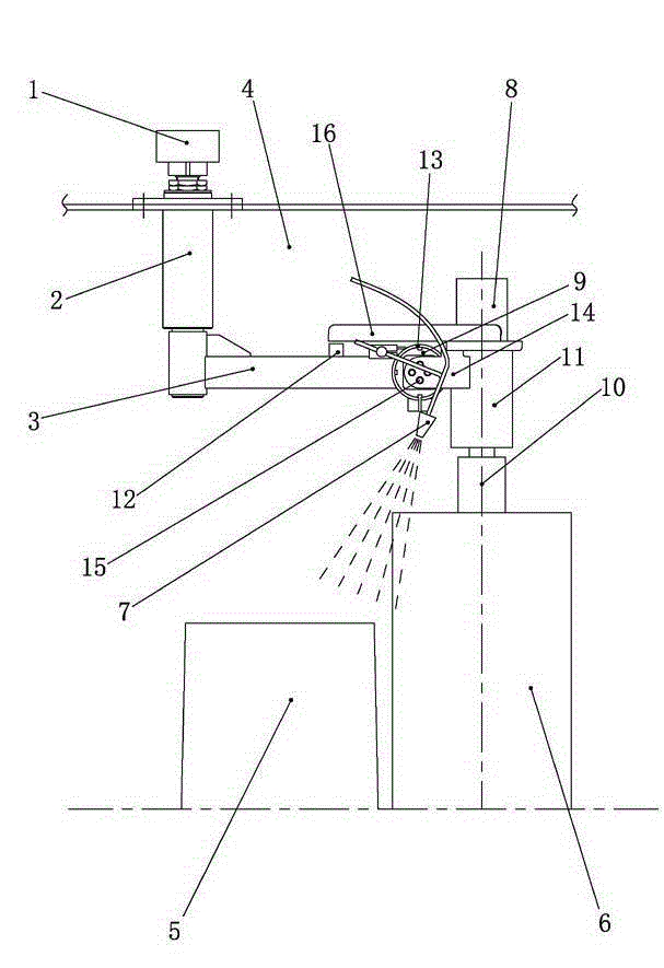
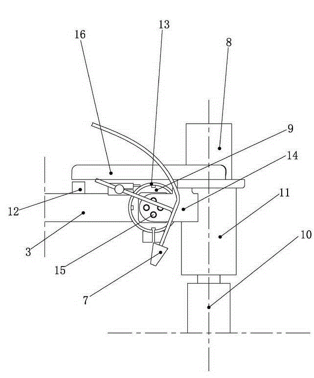
[0017] Such as Figure 1-4 As shown, a garbage can cleaning system includes a driving source 1 fixedly installed on the washing chamber 4, a power main shaft 2 rotatably installed vertically on the output end of the driving source 1, and a rotating arm vertically fixed on the bottom end of the power main shaft 2 3. The scrubbing assembly installed at the end of the rotating arm 3 and the spray mechanism 7 installed on the rotating arm 3; the scrubbing assembly includes a driving motor 8, a fixed base 11, a rotating shaft 10, and a cleaning brush in contact with the outer wall of the trash can 5 6. The axis of the rotating shaft 10 is perpendicular to the extension of the rotating arm 3. The fixed base 11 is installed at the end of the rotating arm 3. The cleaning brush 6 is mounted on the lower section of the rotating shaft 10, and the upper section of the rotating shaft 10 can rotatably pass through the fixed base. 11 is fixedly connected with the output end of the driving mo...


PUM


Abstract

The invention discloses a rubbish can cleaning system and belongs to the technical field of environmental sanitation equipment. The rubbish can cleaning system comprises a driving source, a power spindle, a rotating arm, a rinsing assembly and a spraying mechanism. The rinsing assembly comprises a driving motor, a fixed base, a rotating shaft and a cleaning brush. The axis of the rotating shaft is perpendicular to the extension direction of the rotating arm. A fixed clamping sleeve is fixedly mounted at the end of the rotating arm, and a deflection assembly is fixedly sleeved with the fixed clamping sleeve. The fixed base is fixedly connected with a pair of connecting lug plates. The deflection assembly comprises a central spindle and an outer sleeve body, and the outer sleeve body is sleeved with the fixed clamping sleeve. The cross section of a hollow cavity of the outer sleeve body is square, and the four side faces of the central spindle right face the four corner sides of the hollow cavity of the outer sleeve body. Rubber bodies are plugged between the side faces of the central spindle and the corner sides of the hollow cavity of the outer sleeve body. The two ends of the central spindle are detachably connected with the connecting lug plates. The rubbish can cleaning system can ensure that the cleaning brush has deflection capacity, and accordingly the phenomenon that the outer wall of a rubbish can is abraded due to overlarge contact acting force between the cleaning brush and the outer wall of the rubbish can is avoided.

Description

technical field [0001] The invention relates to the technical field of sanitation equipment, in particular to a trash can cleaning system. Background technique [0002] At present, due to the extensive use of garbage cans in residential areas, factories and other occasions, a large amount of dirt will adhere to the inner and outer walls of the garbage can. In order to remove these dirt, equipment for automatically cleaning the inner and outer walls of the garbage can has been introduced on the market. The equipment is usually installed in a sealed washing room to facilitate the cleaning of the trash can. [0003] The equipment generally includes a driving source fixedly installed on the washing chamber, a power main shaft vertically installed at the output end of the driving source, a rotating arm vertically fixed at the bottom of the power main shaft, a scrubbing assembly installed at the end of the rotating arm, a The spray mechanism on the top; the scrubbing assembly inc...

Claims


Application Information

Patent Timeline
Patent Type & Authority Applications(China)
IPC IPC(8): B08B9/087B08B9/093
CPCB08B9/087B08B9/093
Inventor 陈彪文朝庆
Owner YANGZHOU JINWEI ENVIRONMENTAL PROTECTION TECH CO LTD
Why Eureka
Try Eureka