Specially-shaped compound bag die-cutting machine

A composite bag and die-cutting machine technology, applied in container manufacturing machinery, paper/cardboard containers, box making operations, etc., can solve problems such as low work efficiency and high noise, and achieve improved production efficiency, low noise, and smooth movement. Effect

Active Publication Date: 2015-12-30
WUXI KING MO MACHINERY
View PDF6 Cites 6 Cited by
  • Summary
  • Abstract
  • Description
  • Claims
  • Application Information

AI Technical Summary

Problems solved by technology

At present, the die-cutting machines used in bag production generally have the disadvantages of low work efficiency and high noise, which cannot meet the market demand well.

Method used


Image

  • Specially-shaped compound bag die-cutting machine
  • Specially-shaped compound bag die-cutting machine

Examples


specific Embodiment approach

[0016] The present invention will be further described below in conjunction with specific drawings and embodiments.

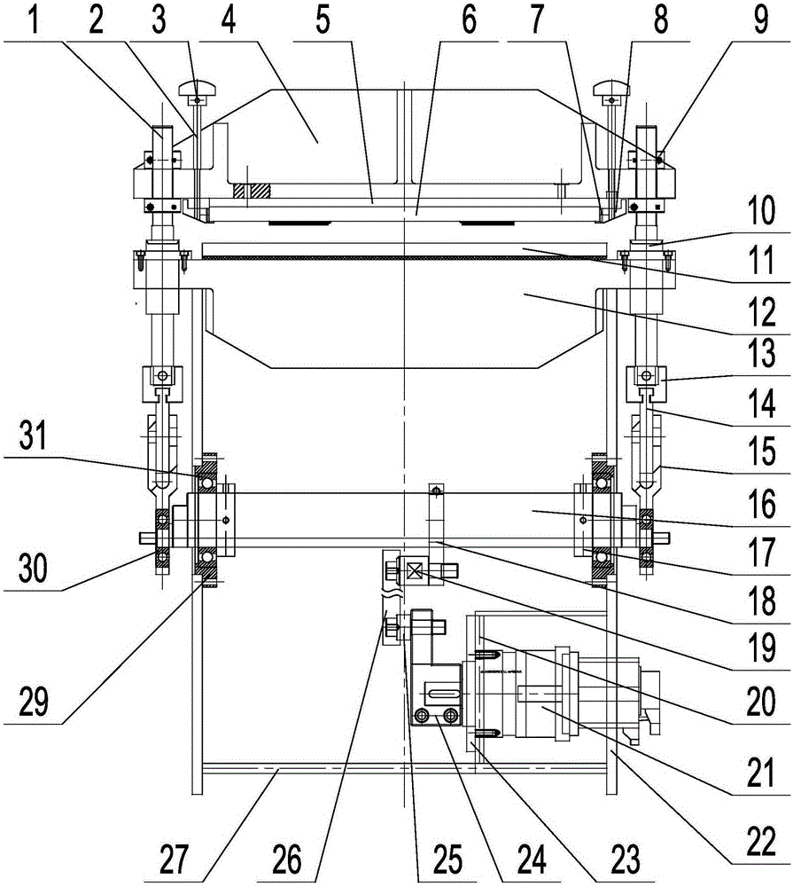
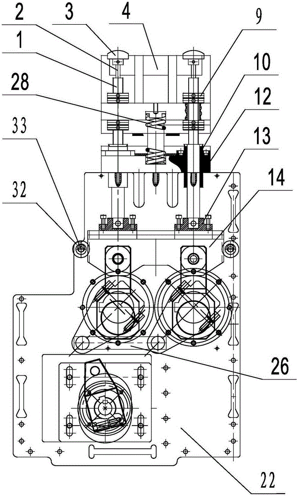
[0017] As shown in the figure: the special-shaped composite bag die-cutting machine in the embodiment is mainly composed of a guide shaft 1, a screw rod 2, an adjustment cap 3, an upper mold base 4, a knife plate 5, a cutter 6, a knife plate 7, a knife holder 8, and a nut 9. Guide sleeve 10, pressure plate 11, lower mold base 12, slider 13, guide plate 14, lifting U-shaped fork 15, eccentric shaft 16, tight ring 17, swing arm 18, first pile head shaft 19, motor bracket 20 , servo motor 21, wall plate 22, motor fixing seat 23, eccentric arm 24, second pile head shaft 25, connecting plate 26, bottom plate 27, spring 28, bearing seat 29, small bearing 30, large bearing 31, positioning bearing 32 And components such as eccentric minor shaft 33 are formed.

[0018] Such as figure 1 , figure 2 As shown, the lower mold base 12 is fixedly installed on the top of t...


PUM


Abstract

The invention relates to a specially-shaped compound bag die-cutting machine which comprises a stander, and is characterized by further comprising guide shafts, an upper die seat, cutter, nuts, guide sleeves, a stamping plate, a lower die seat and a lifting driving mechanism, wherein the lower die seat is fixedly mounted at the top of wall plates on the two sides of the stander; the stamping plate is mounted at the top of the lower die seat; two guide sleeves are respectively mounted at the two ends of the lower die seat; one piece of guide shaft is assembled in each guide sleeve; the lower ends of the guide shafts are connected with the lifting driving mechanism; the upper die seat is arranged right above the lower die seat; mounting holes corresponding to the upper ends of the guide shafts are formed in the two ends of the upper die seat; the upper ends of the guide shafts penetrate through the mounting holes in the upper die seat, and are locked and fixed by two nuts, namely an upper nut and a lower nut; the cutter is mounted at the bottom of the upper die seat; the upper die seat is driven to do lifting motion through the lifting driving mechanism; the upper die seat drives the cutter to be matched with the stamping plate during downward movement, thus realizing die cutting operation. The specially-shaped compound bag die-cutting machine is reasonable in structural design and lower in noise, the production efficiency can be well improved, the synchronism of the motions of two groups of eccentric shafts is guaranteed, and the steadiness of the up and down motions of the four guide shafts is guaranteed.

Description

technical field [0001] The invention relates to a die-cutting machine, in particular to a special-shaped composite bag die-cutting machine used in a bag-making machine, and belongs to the technical field of bag-making machines. Background technique [0002] With the continuous development of the economy, the market's demand for the shape and size of packaging bags has become more and more diverse, making die-cutting machines widely used in the production of special-shaped composite bags. At present, the die-cutting machines used in bag production generally have the disadvantages of low working efficiency and high noise, which cannot meet the market demand well. Contents of the invention [0003] The purpose of the present invention is to overcome the deficiencies in the prior art, and provide a special-shaped composite bag die-cutting machine, which has a reasonable structure design, stable movement, can improve production efficiency, and has low noise, which can ensure tw...

Claims


Application Information

Patent Timeline
Patent Type & Authority Applications(China)
IPC IPC(8): B31B1/20B31B50/20
Inventor 郭林
Owner WUXI KING MO MACHINERY
Why Eureka
Try Eureka