Heavy-duty shuttle wheel side drive system integrating differential transfer and wet brake

A drive system, wet brake technology, applied in the direction of the transmission device driven by the electric motor, can solve the problems of poor steering differential function, large braking impact, etc., achieve small braking impact, high power utilization, and reduce control requirements Effect

Active Publication Date: 2017-10-24
TAIYUAN INST OF CHINA COAL TECH & ENG GROUP +1
View PDF1 Cites 0 Cited by
  • Summary
  • Abstract
  • Description
  • Claims
  • Application Information

AI Technical Summary

Problems solved by technology

[0009] In order to solve the problems of poor steering differential function and large braking impact in the existing shuttle car braking system, the present invention provides a heavy-duty shuttle wheel side drive system integrating differential speed transfer and wet braking

Method used


Image

  • Heavy-duty shuttle wheel side drive system integrating differential transfer and wet brake
  • Heavy-duty shuttle wheel side drive system integrating differential transfer and wet brake
  • Heavy-duty shuttle wheel side drive system integrating differential transfer and wet brake

Examples


Embodiment Construction

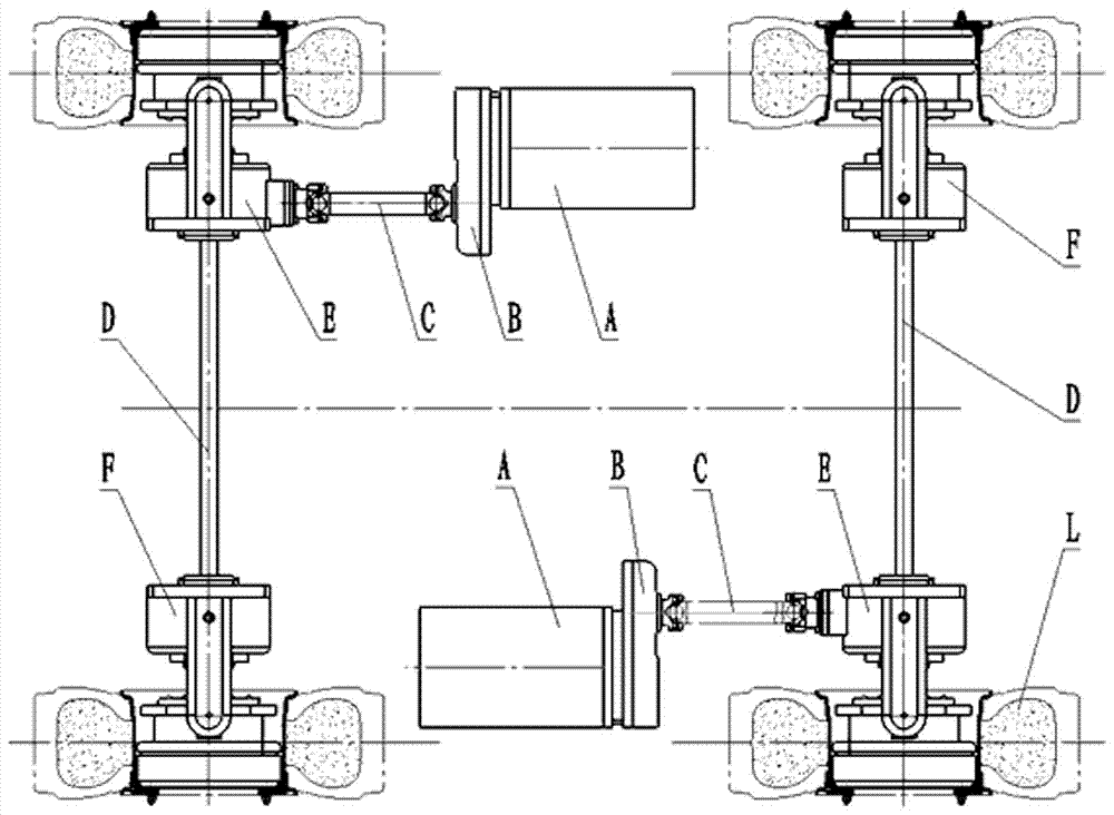
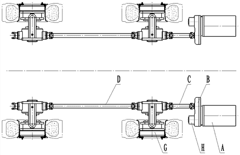
[0029] The present invention is mainly used in mine conditions of medium-thick coal seams, and is applied to heavy-duty shuttle cars (shuttle cars of 20t and above) with larger body height and width. Such as figure 1 As shown, the driving front axle and the driving rear axle of the shuttle car are driven / braked separately, that is, parallel control, and are respectively controlled by the drive system of the present invention. The drive system includes a motor A, a primary speed reducer B, a wheel edge Reducer IE and wheel reducer IIF, wheel reducer IE and wheel reducer IIF are symmetrically installed at both ends of the transverse drive shaft D of the corresponding shuttle car drive axle, and wheel reducer IE and wheel reducer IIF are located at On the inner side of the running rubber wheel L of the shuttle car, the wheel side reducer IE is connected to the output end of the first-stage reducer B through the transmission shaft C, and the first-stage reducer B is driven by the...


PUM


Abstract

The invention belongs to the technical field of design and manufacture of parts and components of underground auxiliary transportation equipment in coal mines. In order to solve the problems of poor steering differential speed and large braking impact in the existing shuttle car braking system, the invention provides a set differential speed A heavy-duty shuttle wheel side drive system integrating transfer and wet brakes. The driving front axle and driving rear axle of the shuttle car are respectively controlled by two sets of parallel drive systems, and each set of drive systems includes a motor, a first-stage Wheel reducer I and wheel reducer II, wheel reducer I and wheel reducer II are symmetrically installed at both ends of the transverse transmission shaft of the corresponding shuttle car drive axle, and wheel reducer I and wheel reducer The device II is located inside the running rubber wheel of the shuttle car, and the wheel-side reducer I is connected to the output end of the first-stage reducer through a transmission shaft, and the first-stage reducer is driven by a motor. The invention utilizes two sets of parallel drive systems, which improves the problems of tire wear and wheel side reducer partial load, and improves the motor power utilization rate.

Description

technical field [0001] The invention belongs to the technical field of design and manufacture of parts of underground auxiliary transportation equipment in coal mines, and in particular relates to a heavy-duty shuttle wheel side drive system integrating differential speed transfer and wet braking. Background technique [0002] At present, domestic and foreign shuttle cars mostly use figure 2 The wheel side transmission system shown adopts the method of driving / braking separately on both sides, and the motor drives the first-stage reducer on both sides, the first-stage reducer drives the transmission shaft, the drive shaft drives the wheel side reducer, and the tire is installed on the wheel. side reducer. The wheel reducer close to the motor simultaneously drives another drive shaft, which drives the other wheel reducer farther away from the motor. [0003] The motors are placed on both sides of the shuttle car, and the reducers on the two wheels are longitudinally arrange...

Claims


Application Information

Patent Timeline
Patent Type & Authority Patents(China)
IPC IPC(8): B61C9/46
Inventor 马福文闫金宝张君杨勤李永安贺克伟马凯张洮慕伟杨杰郑吉吕继双梁大海
Owner TAIYUAN INST OF CHINA COAL TECH & ENG GROUP
Why Eureka
Try Eureka