Method and equipment for improving glass quality

A glass, quality technology, used in/or other glass substrates, clarification and homogenization, the production of glass substrates, can solve the problems of uneven temperature of glass liquid, high temperature of molten glass, stripes and other problems

Inactive Publication Date: 2007-04-18
HENAN ANCAI HI-TECH +1
View PDF0 Cites 19 Cited by
  • Summary
  • Abstract
  • Description
  • Claims
  • Application Information

AI Technical Summary

Problems solved by technology

[0008] Adopting the method of heating the precious metal tube wall in the clarification zone will cause the intermediate molten glass temperature to be low, and the molten glass temperature close to the clarification zone precious metal tube wall to be high
The larger the cross-sectional area of ​​the precious metal in the clarification zone, the more uneven the temperature of the glass liquid, the more uneven the flow of the glass liquid, and glass defect

Method used


Image

  • Method and equipment for improving glass quality
  • Method and equipment for improving glass quality
  • Method and equipment for improving glass quality

Examples


Example Embodiment

[0074] Example 2

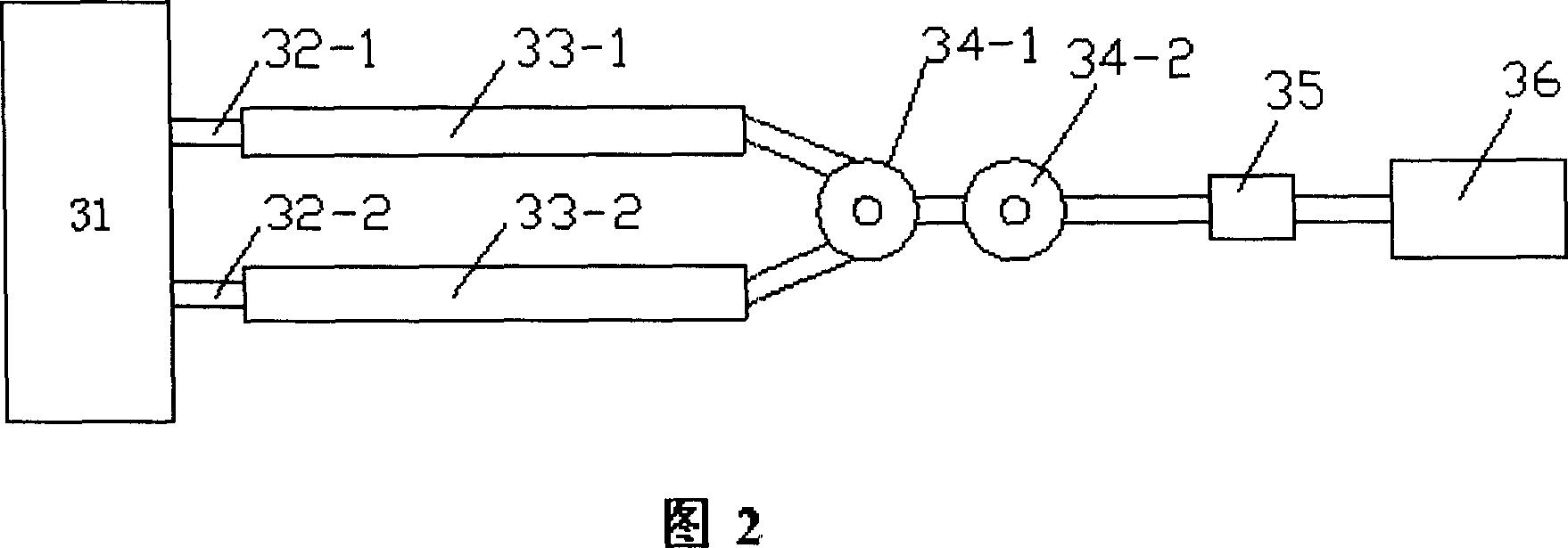
[0075] As shown in Figure 2, this example is two parallel clarification zones. Under the condition of a glass flow rate of 10 tons / day, the clarification zone is designed into a cylindrical shape. According to certain experience and theory, the diameter, wall thickness, and length of the clarification zone are determined as shown in the corresponding row in Example 2 of Table 1. Compared with Comparative Example 1, the amount of precious metals in Example 2 is 20.48 kg less; the glass temperature difference is reduced from ±3°C to ±1°C; the number of bubbles larger than 0.1mm per kg of glass plate does not exceed 0.5; The operating temperature can be reduced from 1680°C to 1650°C; the life of the clarification zone is extended from 21 months to 26 months.

Example Embodiment

[0076] Example 3

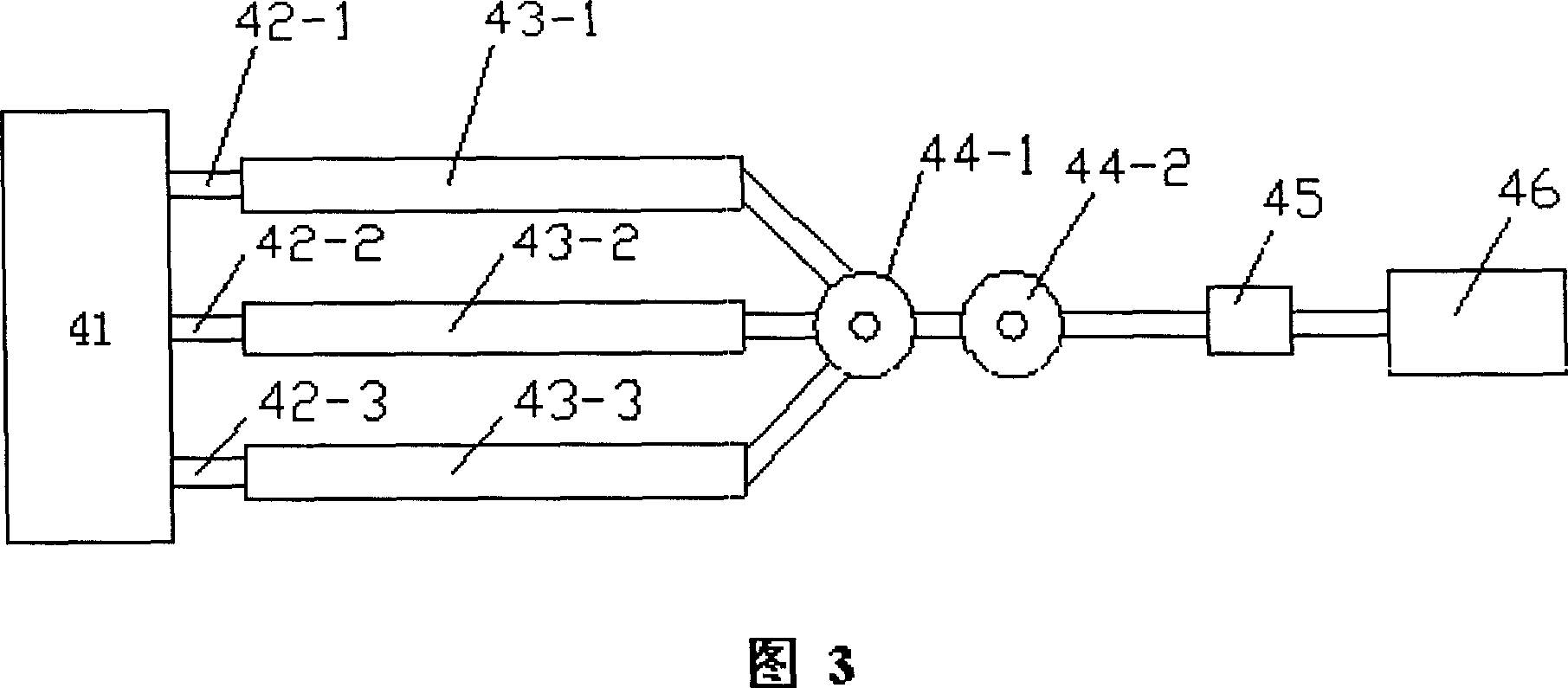
[0077] As shown in Figure 3, this example is three parallel clarification zones. Under the condition of a glass flow rate of 10 tons / day, the clarification zone is designed into a cylindrical shape. According to certain experience and theory, the diameter, wall thickness, and length of the clarification zone are determined as shown in the corresponding row in Example 3 of Table 1. Compared with Comparative Example 1, the amount of precious metals used in Example 3 is 36.65 kg less; the glass temperature difference is reduced from ±3°C to ±0.7°C; the number of bubbles larger than 0.1mm per kg of glass plate does not exceed 0.2; the clarification zone The operating temperature dropped from 1680°C to 1620°C, and the life of the clarification channel was extended from 21 months to 26.5 months.

[0078] Through the above examples, it can be clearly seen that when the glass flow rate is 10 tons / day, the two examples using parallel clarification zones are more effectiv...

Example Embodiment

[0081] Example 5

[0082] As shown in Figure 2, this example is two parallel clarification zones. Under the condition of a glass flow rate of 12 tons / day, the clarification zone is designed into a cylindrical shape. According to certain experience and theory, the diameter, wall thickness, and length of the clarification zone are determined as shown in the corresponding row of Example 5 in Table 1. Compared with Comparative Example 4, the amount of precious metals in Example 5 is 35.68 kg less; the glass temperature difference decreases from ±3.3°C to ±1.5°C; the number of bubbles larger than 0.1mm per kg of glass plate does not exceed 0.6; The operating temperature can be reduced from 1680°C to 1650°C; the life of the clarification zone is extended from 19 months to 24.5 months.


PUM


Abstract

The present invention discloses a method for raising glass quality and its equipment. It includes glass melting furnace, clarifying zone and stirring zone, etc. It is characterized by that between glass melting furnace and stirring zone at least two parallel clarifying zones are set, the molten glass can parallelly flow through said clarifying zones, then can be collected in the stirring zone, so that it not only can meet the requirements for making large flow capacity of molten glass be passed through said clarifying zones, but also can raise glass quality.

Description

technical field [0001] The present invention relates to the clarification of glass. Specifically, the present invention is applied to the production and manufacture of glass substrates, and relates to the clarification and homogenization in the production and manufacture of these products, so as to meet the requirements of high-quality glass products. A particularly important application of the invention is the production of glass substrates for liquid crystal displays, TFTs, etc. and / or others. Background technique [0002] The basic manufacturing of glass used in liquid crystal displays is an advanced technology, and the final glass basically requires no glass defects such as bubbles and streaks. [0003] The general glass substrate production process is that after the glass is melted, the molten glass passes through a clarification zone made of precious metal materials, the melting temperature is raised, and the molten glass is stirred and adjust...

Claims


Application Information

Patent Timeline
IPC IPC(8): C03B5/235C03B5/225
CPCC03B5/225Y02P40/57
Inventor 贾伟李震李耀辉徐建军田红星
Owner HENAN ANCAI HI-TECH
Why Eureka
Try Eureka