Pulsation type turbine shaft engine

A turboshaft engine and turbine group technology, which is applied in the direction of machines/engines, gas turbine devices, mechanical equipment, etc., can solve the problems of heavy weight of the deceleration system, high material requirements, immature technology, etc., and achieve high power-to-weight ratio and mechanical structure Simple, lightens the effect of the deceleration system

Inactive Publication Date: 2008-03-26
张清宇
View PDF3 Cites 5 Cited by
  • Summary
  • Abstract
  • Description
  • Claims
  • Application Information

AI Technical Summary

Problems solved by technology

[0002] It is now commonly used in reciprocating piston gas engines such as automobiles, trains, ships, and machinery. Although they have been improved in many ways, they have significantly improved in terms of power, weight, emissions, and energy consumption compared with the past, but their fundamental shortcomings cannot be eradicated: 1. The reciprocating mechanical movement of the crankshaft, connecting rod, piston and other components itself loses power consumption and damages the mechanical strength
2. The structure of the gas distribution device required is complex and extremely precise
3. Affected by the piston stroke, the fuel combustion is not complete
4. In order to prevent deflagration and knocking, the air compression ratio is limited and too low, resulting in low thermal efficiency, etc.
Although these gas engines have eliminated reciprocating mechanisms such as crankshafts, connecting rods, and pistons, they cannot be widely used due to insufficient or immature technology.
[0004] Turboshaft engines are widely used in aviation and military fields due to their simple structure, high power, large power-to-weight ratio, and high thermal efficiency. The speed is too high and it is not easy to control, which limits its application in automobiles, trains, ships, machinery and other fields

Method used


Image

  • Pulsation type turbine shaft engine

Examples


Embodiment Construction

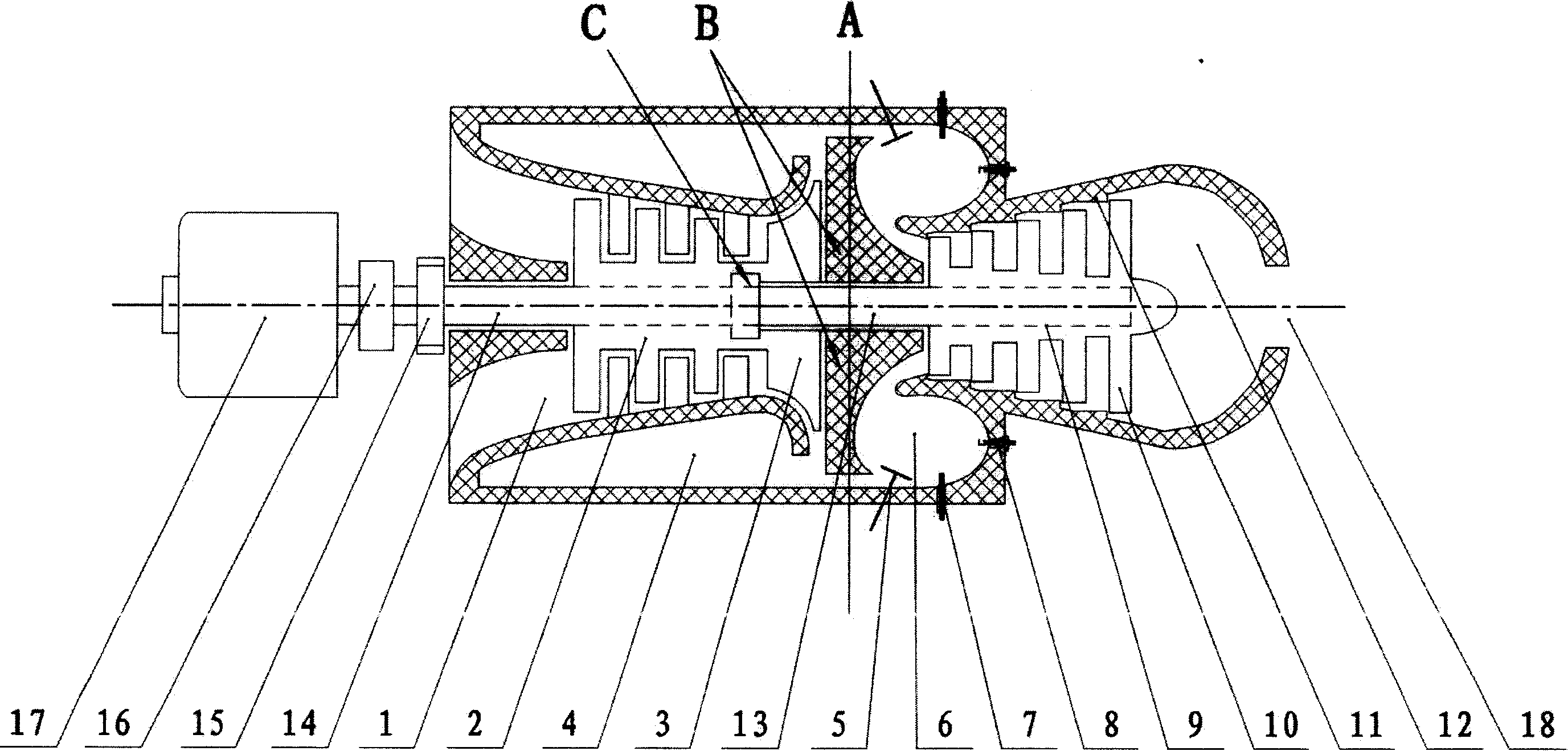
[0022] Accompanying drawing is the structure schematic diagram of the preferred embodiment of the present invention, namely engine is made up of three parts of air compression device, compressed air storage device and mixed gas combustion work device. The air compression device is composed of an axial flow compressor (2) and a centrifugal compressor (3) coaxially; the compressed air storage device is composed of a compressed air storage chamber (4); the mixed gas combustion work device is composed of a combustion chamber (6), The turbine group (9) and gas distribution device, fuel supply device, ignition device and other components. When the engine is started, the starter motor (17) drives the compressors (2) and (3) to rotate through the starter clutch (16), sucks in air from the intake passage (1) for compression, and the compressed air is pressed into the compressed air storage chamber (4) In the process, when the predetermined pressure is reached, the valve (5) opens, and ...


PUM


Abstract

The improved pulsatory turbo shaft engine consists of three assemblies, including one independently running air compressor assembly, one compressed air storing assembly and one mixed gas burning work doing assembly. The air compressor assembly comprising coaxially cascade axial air compressors and centrifugal air compressors is driven by one motor or one turbine combination to produce compressed air to be stored in the compressed air storing bin. Under the control of the air distributing device, compressed air is mixed with fuel inside the combustion chamber to burn, and the heat energy acts directly onto the turbine combination, so that the turbine combination rotates in the controlled direction and rotation speed to output kinetic energy. The engine under the control of the air distributing device runs in the cyclic pulsation mode of 'intake-burning to do work', and has comprehensive performance superior to available gas burning engines.

Description

Technical field: [0001] The invention relates to gas engines, in particular turboshaft engines. Background technique: [0002] It is now commonly used in reciprocating piston gas engines such as automobiles, trains, ships, and machinery. Although they have been improved in many ways, they have significantly improved in terms of power, weight, emissions, and energy consumption compared with the past, but their fundamental shortcomings cannot be eradicated: 1. The reciprocating mechanical movement of the crankshaft, connecting rod, piston and other components itself loses power consumption and damages the mechanical strength. 2. The structure of the required gas distribution device is complex and extremely precise. 3. Affected by the stroke of the piston, the fuel combustion is not complete. 4. In order to prevent deflagration and knocking, the air compression ratio is limited and too low, resulting in low thermal efficiency, etc. [0003] At present, in order to overcome t...

Claims


Application Information

Patent Timeline
Patent Type & Authority Applications(China)
IPC IPC(8): F02C3/04F02C7/057F02C7/00F02C7/28
Inventor 张清宇
Owner 张清宇
Why Eureka
Try Eureka