Sliding door plate and sliding door with sliding door plates

A sliding door and door panel technology, which is applied in the direction of door leaf, door/window fittings, wing leaf arrangement, etc., can solve the problems of difficulty in realizing the exchange of left door and right door, and difficulty in realizing push-pull action.

Active Publication Date: 2015-12-30
CENT INT GROUP
View PDF5 Cites 4 Cited by
  • Summary
  • Abstract
  • Description
  • Claims
  • Application Information

AI Technical Summary

Problems solved by technology

[0003] The pulley is the most important hardware component in the sliding door. At present, most of the sliding doors on the market adopt the structure of installing pulleys at the bottom or both ends of the pulley. The pulley is installed at the lower end of the sliding door, and the lower guide rail is often the bearing point of the weight. If there is foreign matter or dust on the lower guide rail of the sliding door, it is often difficult to realize the sliding action
In addition, different installation environments require door opening methods in different directions, that is, some need to open the door from the left, and some need to open the door from the right. The existing sliding doors need to be customized according to the use environment, and it is difficult to realize the interchange between the left and right doors.

Method used


Image

  • Sliding door plate and sliding door with sliding door plates
  • Sliding door plate and sliding door with sliding door plates
  • Sliding door plate and sliding door with sliding door plates

Examples


Embodiment Construction

[0028] In order to make the object, technical solution and advantages of the present invention clearer, the implementation manner of the present invention will be further described in detail below in conjunction with the accompanying drawings.

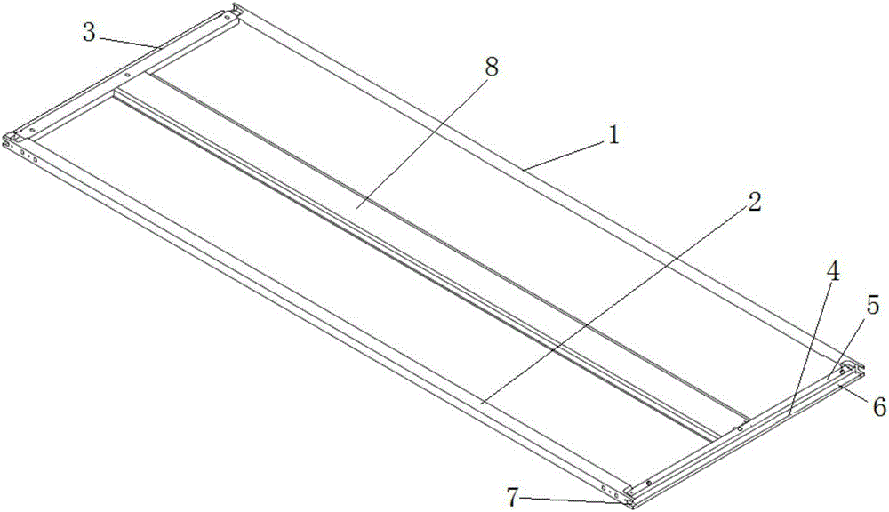
[0029] Such as figure 1 As shown in the structure, the present invention provides a sliding door panel. The door panel is formed by bending a steel plate, and its left and right sides are bent to form a symmetrical left panel frame 1 and a right panel frame 2, and its upper and lower ends are bent. A symmetrical upper frame 3 and a lower frame 4 are formed, and a convex structure 5 parallel to the surface of the door panel is respectively formed on the upper frame 3 and the lower frame 4, and a plurality of screw holes are formed at intervals along the length of the convex structure 5 . Because the upper plate frame 3 and the lower plate frame 4 are symmetrical, and the left plate frame 1 and the right plate frame 2 are symmetrically ...


PUM


Abstract

The invention discloses a sliding door plate and a sliding door with sliding door plates. The door plate is formed by bending a steel plate. The left side and the right side of the door plate are bent to form a left plate frame and a right plate frame which are symmetrical. The upper end and the lower end of the door plate are bent to form an upper plate frame and a lower plate frame which are symmetrical. The upper plate frame and the lower plate frame each form a convex face structure parallel to the plate face of the sliding door plate. A plurality of threaded holes are formed in the convex face structures in the length direction at intervals. The sliding door comprises a door frame, and the first door plate, the second door plate and the third door plate which are connected with the door frame. The first door plate, the second door plate and the third door plate are arranged in a front-back staggered mode. The first door plate is a fixed door plate and is fixed to one side of the door frame. The second door plate and the third door plate are the sliding door plates, the upper end of the second door plate and the upper end of the third door plate are connected with the upper edge of the door frame through pulley baffles in a rolling mode, and the lower end of the second door plate and the lower end of the third door plate are connected with the lower edge of the door frame through a short slide rail and a long slide rail in a sliding mode respectively. By exchanging or replacing the pulley baffles and the slide rails, the leftward door opening mode and the rightward door opening mode can be switched, and replacement is convenient.

Description

technical field [0001] The invention relates to the application technical field of a locker and a sliding door for a cabinet body structure, in particular to a sliding door panel and the sliding door. Background technique [0002] The original sliding door was only used for the sliding door of the bedroom or dressing room wardrobe, but with the development of technology and the diversification of decoration methods, from traditional plate surface to glass, aluminum alloy profiles, from sliding door, folding door to partition door , the function and scope of use of sliding doors are constantly expanding. In this case, the application of sliding doors has become diverse and rich. In addition to the most common partition doors, sliding doors are widely used in bookcases, wall cabinets, living rooms, showrooms, sliding doors, etc. [0003] The pulley is the most important hardware component in the sliding door. At present, most of the sliding doors on the market adopt the stru...

Claims


Application Information

Patent Timeline
Patent Type & Authority Applications(China)
IPC IPC(8): E06B3/46E06B3/72E05D13/00
Inventor 颜坚刘爱森陈俊臣
Owner CENT INT GROUP
Why Eureka
Try Eureka