
a centrifugal pump

A technology of centrifugal pumps and front pumps, applied in the field of centrifugal pumps, which can solve problems that do not involve improving the flow characteristics inside the front chamber, and achieve the effects of weakening disturbances, improving working conditions, and reducing energy loss

Active Publication Date: 2019-05-31
JIANGSU UNIV
View PDF7 Cites 0 Cited by
  • Summary
  • Abstract
  • Description
  • Claims
  • Application Information

AI Technical Summary

Problems solved by technology

[0005] To sum up, the current research does not involve improving the flow characteristics inside the front cavity. The present invention proposes to add a front vane in the pump front cavity to improve the internal flow characteristics, filling the traditional design. It is a new design method about the front chamber of the pump

Method used


Image

  • a centrifugal pump
  • a centrifugal pump

Examples


Embodiment Construction

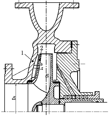
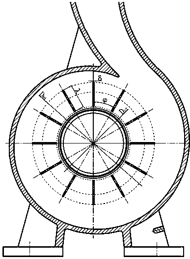
[0017] In the present invention, taking a centrifugal pump as an example, 12 annular blades are arranged inside the front pump cover of the volute, such as figure 2 shown. The angle φ between two adjacent front blades is determined by the number of blades Z, which is 360° / Z. In this example, Z is 12 pieces, then φ=30°; the inlet diameter of the front blades is D b1 According to formula D b1 =(0.95~1)×D2, determined by the impeller outer diameter D2, in this example D2=240 mm, D b1 =228mm, the outlet diameter D of the front blade b2 by D b2 =(1.1~1.3)×Ds, Ds is impeller inlet diameter, in this example D b2 =140mm. Such as figure 1 As shown, the diameter of the outlet of the front blade is above the mouth ring, and the meridian section of the front cavity shrinks rapidly; the length of the front blade λ=(D b1 -D b2 ) / 2, in this example λ=44 mm. The height of the front blade changes due to the change of the geometric structure of the front cavity. The gap τ between the ...


PUM


Abstract

The invention relates to the field of fluid machinery, particularly a centrifugal pump. The centrifugal pump is characterized in that a front blade for improving the flow properties in the front cavity is arranged between a front pump cover and an impeller front cover plate. The fluid at the impeller exit enters the front blade via the junction between the front cavity and volute casing inlet; the vortex intensity of the fluid is reduced under the action of the front blade, thereby reducing the energy loss and enhancing the efficiency; and the energy of the fluid is lowered after passing through the front blade, and the disturbance generated by mixing with the impeller entrance low-energy fluid is reduced, thereby improving the impeller inflow condition.

Description

technical field [0001] The patent of the invention relates to the field of fluid machinery, in particular to a centrifugal pump, which improves the fluid flow characteristics in the chamber by adding a front blade between the front pump cover and the front cover plate of the impeller. Background technique [0002] Pumps are widely used in fields such as agriculture, chemical industry, aerospace, navigation, food processing, and electric power, so the improvement of pump performance has important social value; The focus of attention, while the flow characteristics in the cavity between the pump body and the impeller are limited, especially the front cavity communicates with the impeller inlet and outlet, which directly affects the working conditions of the impeller, and the fluid leaking through it will not only cause volume loss , will cause energy loss due to mixing with the inlet fluid, so improving the flow characteristics in the front cavity has very great social signifi...

Claims


Application Information

Patent Timeline
Patent Type & Authority Patents(China)
IPC IPC(8): F04D29/24
Inventor 高波王震张宁杜文强
Owner JIANGSU UNIV
Learn More