A Method for Improving the Hydraulic Flow State of Diffusion Divider Basin

A diffusion-type diversion pool technology, applied in river regulation and other directions, can solve problems such as flow disorder in diversion pools, washing bank slopes, bad flow conditions, etc., and achieve the effect of simple structure and easy construction and production

Active Publication Date: 2020-01-17
HOHAI UNIV
View PDF8 Cites 0 Cited by
  • Summary
  • Abstract
  • Description
  • Claims
  • Application Information

AI Technical Summary

Problems solved by technology

The joint construction of pumps and gates solves the problem of large-scale land acquisition. However, due to the compact layout of the buildings, bad flow patterns are likely to occur in the water intake system of the joint construction of pumps and gates. Severe spiral flow, backflow and lateral flow are caused, which deteriorate the water inlet flow state of the pumping station and sluice, thereby reducing the discharge capacity of the sluice, the operating efficiency of the pumping station and the operation stability of the unit. In severe cases, it will wash the bank slope, aprons, etc., endangering the safety of the pump-sluice joint construction hub project

Method used


Image

  • A Method for Improving the Hydraulic Flow State of Diffusion Divider Basin
  • A Method for Improving the Hydraulic Flow State of Diffusion Divider Basin
  • A Method for Improving the Hydraulic Flow State of Diffusion Divider Basin

Examples


Embodiment 1

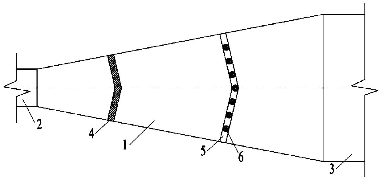
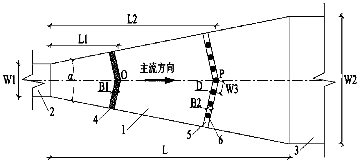
[0030] The schematic diagram of the plane and elevation structure dimensions of the diffusion type split flow pool with the compound rectification device proposed by the present invention in this embodiment is as follows figure 2 , 3 shown.

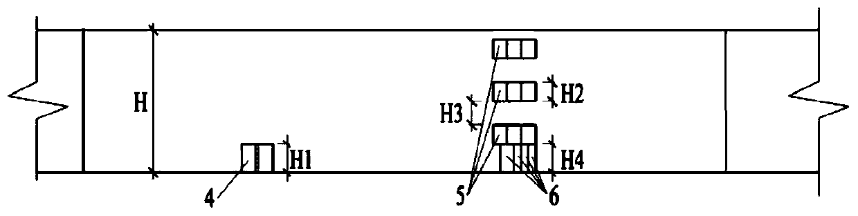
[0031] The length of the diffusion type splitter tank is L=40m, the diffusion angle α=30°, the water depth in the splitter tank is H=5m, the inlet width of the diffusion type splitter tank is W1=5m, the outlet width is W2=25.706m, and the height of the bottom plate is H1=0.2H=1m , Width B1=0.02L=0.8m, distance L1=0.3L=12m from the center point O of the V-shaped sill to the entrance of the diffusion type splitter tank, the number of beams N1=4, the width of the beams B2=0.02L=0.8m, The height of the single-layer beam H2=0.1H=0.5m, the distance between two adjacent beams H3=0.1H=0.5m, the distance between the center point P of the V-shaped composite beam and the entrance of the diffusion type splitter pool L2=0.5L=20m, The height of cyli...

Embodiment 2

[0033] The composite rectifying device described in this embodiment is different from Embodiment 1 in that: the height of the bottom plate H1=0.3H=1.5m, the width B1=0.03L=1.2m, and the distance between the center point O of the V-shaped bottom sill is diffuse type The distance of the entrance of the diversion pool L1=0.2L=8m, the number of beams N1=3, the width of the beams B2=0.03L=1.2m, the height of the single-layer beams H2=0.16H=0.8m, the distance between the two adjacent beams H3=0.2H=1m, distance L2=0.6L=24m from the center point P of the V-shaped composite beam to the entrance of the diffusion type splitter tank, the height of the cylindrical pier H4=0.2H=1m, the cross-sectional diameter of the cylindrical pier D=B2=1.2 m, the number of cylindrical piers N2=7 and N=3, the distance between two adjacent cylindrical piers W3=0.3W1=1.5m.

Embodiment 3

[0035] The composite rectification device described in this embodiment differs from Embodiments 1 and 2 in that: the height of the bottom plate H1=0.4H=2m, the width B1=0.05L=2m, and the distance between the center point O of the V-shaped bottom sill is diffuse type The distance of the inlet of the diversion pool L1=0.1L=4m, the number of beams N1=2, the width of the beams B2=0.05L=2m, the height of the single-layer beams H2=0.2H=1m, the distance between two adjacent beams H3= 0.3H=1.5m, the distance L2=0.7L=28m from the center point P of the V-shaped composite beam to the entrance of the diffusion type splitter tank, the height of the cylindrical pier H4=0.3H=1.5m, the cross-sectional diameter of the cylindrical pier D=B2=2m , the number of cylindrical piers N2=3 and N=1, the distance between two adjacent cylindrical piers W3=0.4W1=2m.

[0036] Such as Figure 4 As shown, the three-dimensional flow numerical simulation method is used to compare and analyze the vertical avera...


PUM


Abstract

The invention discloses a method for improving the hydraulic flow state of a diffusion-type diversion pool. The diffusion-type diversion pool of a water inlet system of a pump-gate co-construction junction is internally provided with a composite rectifying device composed of a V-shaped sill and a V-shaped composite beam with cylindrical piers. According to the method, forward inlet flow of the diffusion-type diversion pool is rectified by the V-shaped bottom sill to achieve full diffusion of the water flow, the flow velocity distribution of the water flow on the horizontal surface is improved,the water flow is further adjusted by the V-shaped composite beam with the cylindrical piers, the flow velocity distribution of the water flow on the vertical surface and the flow velocity distribution of the water flow at the pool bottom on the horizontal surface are equalized, the purpose of comprehensively improving the hydraulic flow state in the diffusion-type diversion pool is achieved, good inlet flow conditions are provided for the pump-gate co-construction junction accordingly, and the method has important engineering application value for ensuring safe, stable and efficient runningof the pump-gate co-construction junction. The composite rectifying device is simple in structural form, easy to construct and manufacture and suitable for application and popularization in design andreconstruction engineering of the pump-gate co-construction junction of the diffusion-type diversion pool.

Description

technical field [0001] The invention belongs to the technical field of pump-sluice joint construction hub engineering, and in particular relates to a method for improving the hydraulic flow state of a diffusion type diversion tank. Background technique [0002] In order to comprehensively solve the problems of urban river flood control and drainage, navigation, water quality improvement and ecological environment, a large number of pump gate hub projects have been built. The sluice and pumping station in the traditional pump-sluice hub project are usually arranged separately. Although this is beneficial to the smooth connection of the upstream and downstream water flow of the hub project, the traditional layout method is too evacuated and occupies a large area, which is easy to cause demolition and damage in urban water conservancy construction. resettlement and other issues. The pump-sluice joint construction hub project has become a hub layout commonly used in plain areas...

Claims


Application Information

Patent Timeline
Patent Type & Authority Patents(China)
IPC IPC(8): E02B3/02
CPCE02B3/02
Inventor 张睿徐辉陈毓陵冯建刚王晓升
Owner HOHAI UNIV
Why Eureka
Try Eureka