Coupling with elastic spider

A technology of elastic coupling and semi-coupling, which is applied in the direction of elastic coupling, coupling, mechanical equipment, etc., can solve the problems of high maintenance cost, insufficient adaptability, complex coupling structure, etc. The effect of prolonging the service life and improving the smooth operation

Inactive Publication Date: 2015-12-30
ZHENJIANG SUODA COUPLING
View PDF8 Cites 13 Cited by
  • Summary
  • Abstract
  • Description
  • Claims
  • Application Information

AI Technical Summary

Problems solved by technology

The existing coupling structure is relatively complex, requires frequent

Method used


Image

  • Coupling with elastic spider
  • Coupling with elastic spider
  • Coupling with elastic spider

Examples


specific Embodiment approach

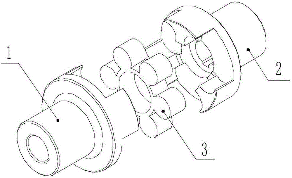
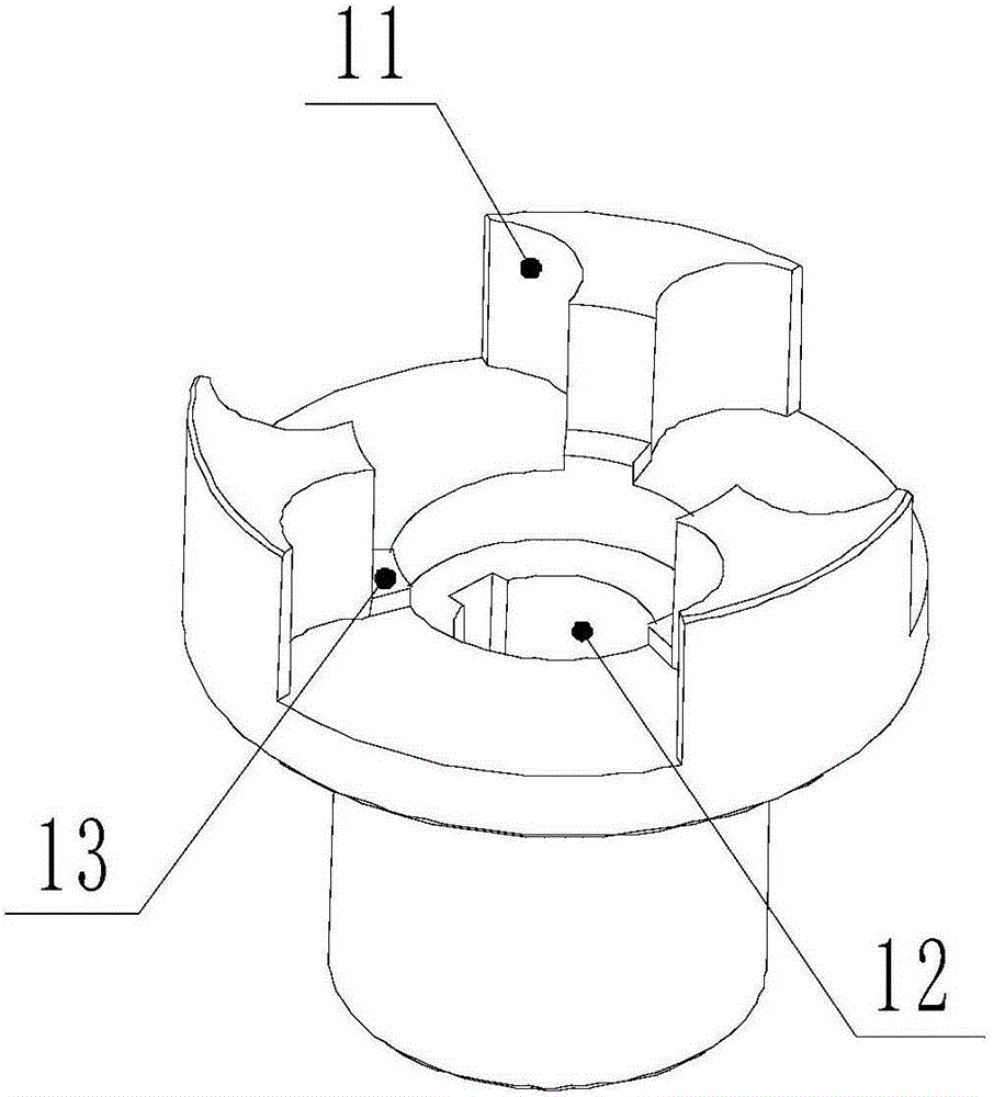
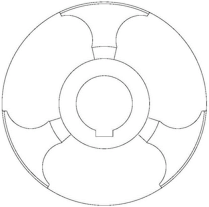
[0017] Examples such as figure 1 , figure 2 and image 3 As shown, a plum-blossom elastic coupling includes a left half-coupling 1, a right half-coupling 2 and a plum-blossom elastic body 3; hole 12, the end faces of the left half-coupling 1 and the right half-coupling 2 are provided with quincunx-shaped protruding teeth 11, and the center position of the quincunx elastic body 3 is provided with a cylindrical hole, and the left half-coupling Bosses 13 are provided on both the device 1 and the right half coupling 2 and are located inside the protruding teeth 11. The two sides of the protruding teeth 11 are concave arc-shaped. Between the half-couplings 2 , the cylindrical boss of the quincunx-shaped elastic body 3 is placed in the gap between the protruding teeth 11 of the left half-coupling 1 and the right half-coupling 2 .

[0018] Preferably, a keyway is processed in the center hole 12 of the left half coupling 1 .

[0019] Preferably, a keyway is processed in the cente...


PUM


Abstract

The invention discloses a coupling with an elastic spider. The coupling mainly comprises a left half coupling, a right half coupling and the elastic spider, wherein both the left half coupling and the right half coupling are provided with center holes, quincuncial double wedges are arranged on the end face of the left half coupling and the right half coupling respectively, a cylindrical hole is formed in the center of the elastic spider, bosses are arranged on the left half coupling and the right half coupling respectively and are located on the inner sides of the double wedges, the two side faces of each double wedge are shaped like concave arcs, the elastic spider is installed between the left half coupling and the right half coupling, and a cylindrical boss of the elastic spider is installed in a gap between the double wedges of the left half coupling and the right half coupling.

Description

technical field [0001] The invention relates to the technical field of shaft couplings, in particular to a quincunx elastic shaft coupling. Background technique [0002] Due to various reasons, the center of mass or the main axis of inertia of the coupling does not coincide with the axis of rotation, and the phenomenon of unbalanced centrifugal inertial force, centrifugal inertial couple force and dynamic deflection (mode shape) will occur during operation. This unbalanced phenomenon is inevitable. Vibration of the shaft system is caused, which affects the error, the deformation of the shaft under load, the deformation of the base, the wear of the bearing, and the temperature change (thermal expansion and contraction) affect the normal operation and service life of the machine. The two shafts connected by the coupling are due to Relative displacement is caused by various factors such as manufacturing errors, installation, and relative movement between components. In general...

Claims


Application Information

Patent Timeline
IPC IPC(8): F16D3/56
CPCF16D3/68
Inventor 王召景纪星文刘蓉李林刘欠欠
Owner ZHENJIANG SUODA COUPLING
Why Eureka
Try Eureka