Sealing ring and mechanical sealing device with same

A sealing ring and sealing end technology, which is applied in mechanical equipment, engine sealing, engine components, etc., can solve problems such as difficult to process, impossible to process directly, and poor processability

Inactive Publication Date: 2015-12-30
霍凤伟
View PDF10 Cites 1 Cited by
  • Summary
  • Abstract
  • Description
  • Claims
  • Application Information

AI Technical Summary

Problems solved by technology

These non-equal-depth grooves generally have the characteristics of fine structure, high precision, and strict roughness requirements. The machinability is generally poor. Processing to approximate forming, there are deficiencies in processing accuracy and surface roughness

Method used


Image

  • Sealing ring and mechanical sealing device with same
  • Sealing ring and mechanical sealing device with same
  • Sealing ring and mechanical sealing device with same

Examples


Embodiment 1

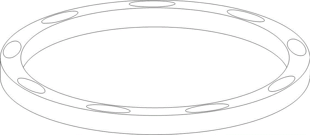
[0094] Example 1: Please refer to figure 1 , figure 2 , image 3 , Figure 4 and Figure 5 .

[0095] A sealing ring has a flat sealing end surface, and a shallow groove is arranged on the sealing end surface, the bottom surface of the shallow groove is a curved surface, and the bottom surface of the shallow groove is inclined by a sealing end surface with a diameter of 175 mm and is flat The circle with an angle of 0.027 radians is a curved surface obtained after elastic recovery of the smooth continuous curved surface formed when the elastically deformed sealing ring that has deformed the sealing end surface into a non-planar surface moves according to the law of motion. The elastic deformation is the elastic deformation that the inner periphery of the sealing end surface of the sealing ring is 57 microns higher than the outer periphery after a force load uniformly distributed along the circumferential direction is applied to the sealing ring. The said movement rule is...

Embodiment 2

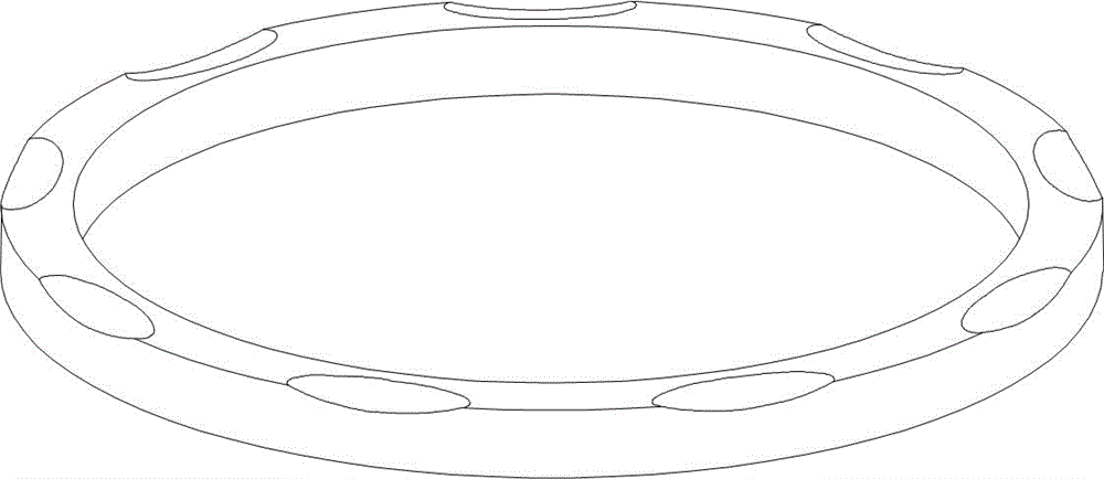
[0097] Example 2: Please refer to Figure 6 , Figure 7 , Figure 8 and Figure 9 .

[0098] A sealing ring has a flat sealing end surface, and a shallow groove is arranged on the sealing end surface, the bottom surface of the shallow groove is a curved surface, and the bottom surface of the shallow groove is inclined by a sealing end surface with a diameter of 175 mm and is flat The circle with an angle of 0.001 radians is a curved surface obtained after elastic recovery of the smooth continuous curved surface formed when the elastically deformed sealing ring that has deformed the sealing end surface into a non-planar surface moves according to the law of motion. The elastic deformation is the elastic deformation that the inner periphery of the sealing end surface of the sealing ring is 24 microns higher than the outer periphery after the force load uniformly distributed along the circumferential direction is applied to the sealing ring. The said motion law is a composite...

Embodiment 3

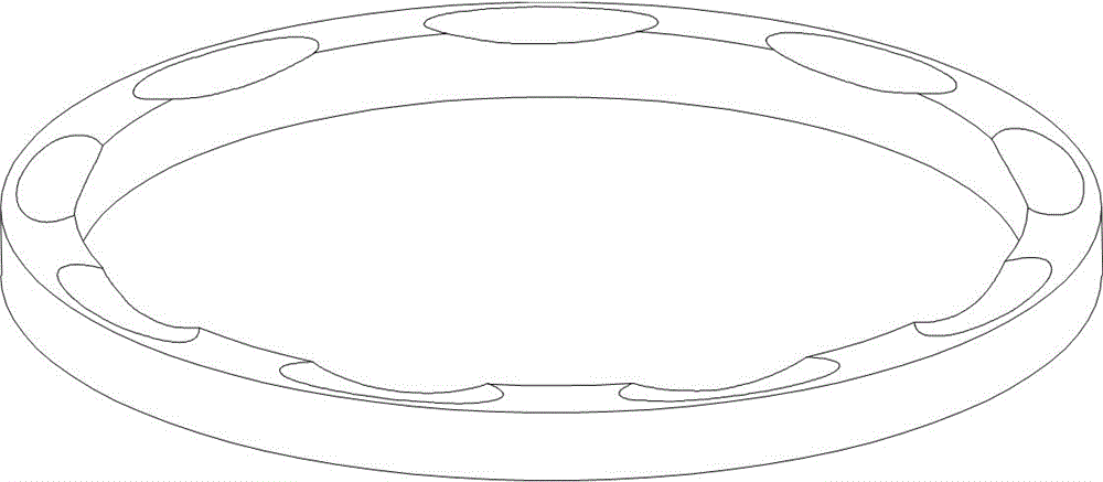
[0099] Example 3: Please refer to Figure 10 and Figure 11 .

[0100] The difference from Embodiment 1 lies in the shape of the shallow groove. In this embodiment, the shallow groove opens on the outer periphery of the sealing end surface.


PUM


Abstract

The invention provides a sealing ring which is characterized in that the sealing end face of the sealing ring is provided with a shallow groove, and the bottom face of the shallow groove is a curved face, wherein the curved face is obtained after elastic recovery of a smooth and continuous curved face, the smooth and continuous curved face is formed in the mode that a circle moves on the sealing ring which has generated elastic deformation making the sealing end face be deformed into a non plane according to a law of motion. The invention further provides a mechanical sealing device with the sealing ring, and the mechanical sealing device is applicable to various types of mechanical sealing. Compared with an existing sealing ring with the sealing end face provided with a flat bottom and other deep grooves and shallow grooves, the thickness or rigidity of a fluid film is larger under the same condition, stability and reliability are higher, and the service life is longer. Compared with an existing sealing ring of a shallow groove with the groove bottom being an inclined plane, or the groove bottom being multi-level flat bottom steps or multi-level inclined bottom steps, the face shape of the bottom face of the shallow groove is consistent with the grinding machining surface generation principle, machining accuracy is high, and the cost is low.

Description

technical field [0001] The invention belongs to the field of mechanical seal seal rings, and relates to a seal ring with a shallow groove on the seal end face, in particular to a seal ring with a shallow groove whose bottom is a curved surface on the seal end face, and also relates to a seal ring with a shallow groove on the seal end face. The mechanical sealing device of the sealing ring is suitable for various forms of contact mechanical seals and non-contact mechanical seals. Background technique [0002] Mechanical seals are widely used in rotating equipment such as pumps, compressors, reactors, agitators, centrifuges and filters that transmit or process various fluids. In the mechanical seal, the dynamic seal ring (also known as the dynamic ring) rotates with the shaft, and is closely fitted with the static seal ring (also known as the static ring) to form the main seal to prevent the leakage of the sealing medium. The performance of the mechanical seal mainly depends ...

Claims


Application Information

Patent Timeline
Patent Type & Authority Applications(China)
IPC IPC(8): F16J15/34
Inventor 霍凤伟
Owner 霍凤伟
Why Eureka
Try Eureka