
A Relative Radiation Correction Method for Mid-Wave Infrared Focal Plane Array Detectors

A technology of relative radiation correction and array detectors, applied in radiation pyrometry, optical radiation measurement, instruments, etc., can solve the problem of low relative radiation correction accuracy of mid-wave infrared focal plane array detectors, and achieve strong engineering application significance Effect

Active Publication Date: 2018-12-18
CHINA CENT FOR RESOURCES SATELLITE DATA & APPL
View PDF3 Cites 0 Cited by
  • Summary
  • Abstract
  • Description
  • Claims
  • Application Information

AI Technical Summary

Problems solved by technology

[0005] The technical problem to be solved by the present invention is: to overcome the deficiencies of the prior art, to provide a relative radiation calibration method of the mid-wave infrared focal plane array detector, and to solve the relative radiation calibration accuracy of the mid-wave infrared focal plane array detector in the background technology. low technical issues

Method used


Image

  • A Relative Radiation Correction Method for Mid-Wave Infrared Focal Plane Array Detectors
  • A Relative Radiation Correction Method for Mid-Wave Infrared Focal Plane Array Detectors
  • A Relative Radiation Correction Method for Mid-Wave Infrared Focal Plane Array Detectors

Examples


Embodiment Construction

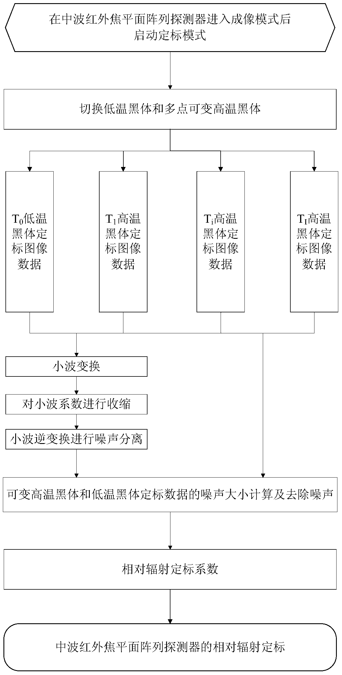
[0018] (1) Establishment of the detector radiation response model: based on the imaging principle of the mid-wave infrared focal plane array detector, fully considering the noise source of the imaging link, the radiation response model of the mid-wave infrared focal plane array detector is established;

[0019] DN(m,n)=f[L(m,n)]+N f (m,n)+N w (m, n) ①

[0020] =f[L(m,n)]+N(m,n)

[0021] In the formula: m, n are the probe position m∈[1, M] of the mid-wave infrared focal plane array detector,

[0022] n ∈ [1, N];

[0023] DN(m, n) is the original digital DN value of the probe (m, n);

[0024] f[L(m,n)] is the function of the radiance L(m,n) received by the probe (m,n);

[0025] N f (m, n) is the generalized 1 / f noise of the probe (m, n);

[0026] N w (m, n) is the white noise of the probe (m, n);

[0027] N(m,n)=N f (m,n)+N w (m, n) is the total noise of detector (m, n).

[0028] (2) On-board blackbody calibration and imaging: complete the imaging of the variable hig...


PUM


Abstract

The invention provides a relative radiation correction method for a medium-wave infrared focal plane array detector. The relative radiation correction method comprises the steps that a detector radiation responding model is firstly built, and then imaging on a variable high-temperature blackbody radiation source and a low-temperature blackbody radiation source is completed to obtain a DN value of a corresponding array detector; wavelet transformation is performed on the DN value of the array detector, a wavelet coefficient of generalized 1 / f noise is estimated according to the counting self-similarity characteristic of the generalized 1 / f noise, then the obtained wavelet coefficient is shrunk through a wavelet soft threshold method, and finally wavelet inverse transformation is performed on the shrunk wavelet coefficient to obtain a medium-wave infrared focal plane array detector DN value after the generalized 1 / f noise is separated is obtained; the noise amplitude is calculated; noise removal is performed on DN values of variable high-temperature blackbody and low-temperature blackbody data; a relative radiation calibration coefficient is obtained through calculation; a relative radiation correction image of the array detector is obtained according to image data obtained by the array detector.

Description

technical field [0001] The invention relates to a relative radiation correction method of a mid-wave infrared focal plane array detector, in particular to a relative radiation correction method of a mid-wave infrared focal plane array detector equipped with an on-board black body calibration device. Background technique [0002] The temperature of the earth's surface is generally 300K, and the radiation energy of the earth's surface is basically in the band above 3.0 μm. The mid-wave infrared focal plane array detector uses the space optical system to collect the mid-wave infrared radiation energy of 3.0 μm to 5.0 μm, which has the ability to penetrate smoke , dust, fog, snow, and the ability to identify camouflage, and can conduct quasi-all-weather observations in day and night. Temperature, ocean surface temperature, day and night cloud, coastline monitoring and other civil applications have a wide range of applications. [0003] However, because the mid-wave infrared foc...

Claims


Application Information

Patent Timeline
Patent Type & Authority Patents(China)
IPC IPC(8): G01J5/52
Inventor 王爱春傅俏燕闵祥军陆书宁潘志强李晓进韩启金张学文刘李李照洲
Owner CHINA CENT FOR RESOURCES SATELLITE DATA & APPL
Learn More