Rotary motor

A technology of rotating motor and rotating shaft, applied in the direction of magnetic circuit rotating parts, magnetic circuit shape/style/structure, etc., can solve the problems of high cost and high price of rotating motor, reduce the amount of magnets, prevent shaking, and improve the strength. Effect

Inactive Publication Date: 2015-12-30
NEW SUN OVERSEA +5
View PDF5 Cites 0 Cited by
  • Summary
  • Abstract
  • Description
  • Claims
  • Application Information

AI Technical Summary

Problems solved by technology

However, permanent magnets with trapezoidal cross-sections are more expensive than those with rectangular cross-sections, and there is a problem that a large amount of cost is required to manufacture rotating motors.

Method used


Image

  • Rotary motor
  • Rotary motor
  • Rotary motor

Examples


Embodiment 1

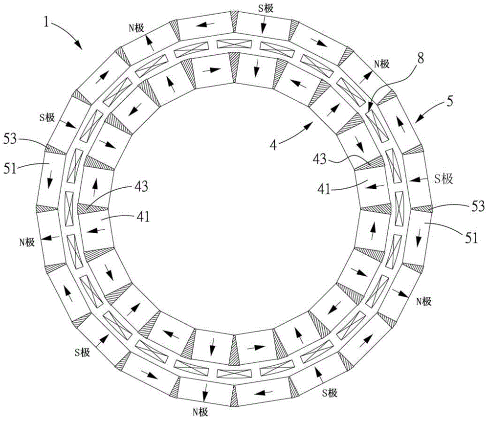
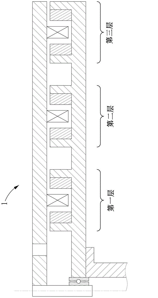
[0044] Use like figure 1 The permanent magnet with rectangular section shown, the ring-shaped double-layer Holbeck excitation system is as image 3 Consists of 3 layers. Nothing is inserted in the wedge-shaped gap between the permanent magnets, so that air is in between. The density of magnetic field lines in the circumferential direction of the interval between the first layer and the third layer Figure 4 , 5 Said.

Embodiment 2

[0046] Use like figure 1 The permanent magnet with rectangular section shown, the ring-shaped double-layer Holbeck excitation system is as image 3 Consists of 3 layers. In the wedge-shaped gap between the permanent magnets, insert iron that can fill the wedge-shaped gap. The density of magnetic force in the circumferential direction at the center of the interval between the first layer and the third layer Image 6 , 7 Said.


PUM


Abstract

The invention discloses a rotary motor. The rotary motor is a double-layer Halbach type excitation rotary motor which can assist in decreasing manufacturing cost. The rotary motor comprises permanent magnets of which the sections are rectangle-shaped and are vertical to the rotation shaft; the permanent magnets are distributed annularly; the permanent magnets of which the sections are rectangle-shaped are distributed at intervals and are separated from each other by the same angle so as to form a ring-shaped structure; filling materials are inserted in wedge-shape slots between adjacent magnets; and the filling materials are composed of a non-magnetic material and a non-electric conduction material. With the above technical schemes of the invention adopted, the rotary motor can be manufactured with low cost. The permanent magnets of which the sections are rectangle-shaped and are vertical to the rotation shaft, are adopted, and therefore, cost for manufacturing the rotary motor can be decreased; the permanent magnets are used in such a manner, so that the consumption of magnets can be decreased, and resources can be saved; the filling materials are inserted between the adjacent permanent magnets, and therefore, the positions of the permanent magnets can be determined conveniently, and the permanent magnets can have sections vertical to the rotation shaft.

Description

Technical field [0001] The present invention relates to rotating electric machines such as ironless motors and ironless generators. Specifically, it relates to rotating electric machines that use permanent magnets arranged in a ring-shaped Holbeck arrangement. Background technique [0002] Normal motors and generators use permanent magnets with N poles and S poles arranged alternately. Such an arrangement will generate magnetic fields on both sides of the front and back sides of the magnet arrangement, making it impossible to effectively use the magnetic field. Therefore, in order to increase the magnetic field of motors and generators, it has been proposed to use a magnet arrangement structure called "Holbeck arrangement". [0003] Since the Halbach arrangement is formed by rotating the permanent magnets by 90 degrees, the magnetic field is weakened on one side of the magnet arrangement, and the magnetic field on the other side is strengthened, so that the unilateral magnetic fiel...

Claims


Application Information

Patent Timeline
IPC IPC(8): H02K1/22
Inventor 蔡镇州辜圣允芦田拓也横山修一森下明平
Owner NEW SUN OVERSEA
Why Eureka
Try Eureka