

Top plate of concentrating solar module
A concentrating solar energy and roof technology, which is applied to photovoltaic power generation, photovoltaic modules, electrical components, etc., can solve the problems of inconsistent lens focal length, affecting the conversion efficiency of concentrating solar modules, and unable to guarantee the fixed position of the lens, and achieve a completely consistent focal length. Effect
Inactive Publication Date: 2015-12-30
成都聚合科技有限公司
View PDF3 Cites 0 Cited by
- Summary
- Abstract
- Description
- Claims
- Application Information
AI Technical Summary
Problems solved by technology
The lens on the concentrating solar module is composed of toughened glass and many small lenses, so when designing and installing the lens, it is necessary to consider how to fix the lens to ensure that the focal length of each small lens is consistent. The existing design and installation use 4 pieces of metal strips fix the 4 end faces of the lens on the frame of the concentrating solar module respectively. This fixing method cannot guarantee the fixed position of the lens. At the same time, because the 4 end faces are respectively fixed, the force of the 4 end faces of the lens cannot be guaranteed to be consistent. As a result, the lens is not installed horizontally, which will cause the focal length of each small lens to be inconsistent, that is, the focal spot where the sun's rays are converged to the concentrating solar cell chip through the lens is different, which will seriously affect the concentration of solar energy. Component Conversion Efficiency
Method used
View moreImage
Smart ImageViewing Examples

Examples
Embodiment Construction
[0011] The present invention will be further described below in conjunction with the accompanying drawings.
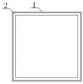
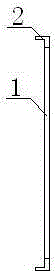
[0012] A concentrated solar module roof, such as Figure 1~2 As shown, it includes a top plate 1 and a lens fixing groove 2. There is a lens fixing groove 2 on the top plate 1. When in use, the lens is first placed on the frame of the concentrated solar module, and then the lens fixing groove of the top plate 1 is aligned. The quasi-lens is placed on the top of the lens, and finally the top plate 2 is fixed with screws, so that the lens can be accurately positioned effectively, and the focal length of each small lens can be guaranteed to be completely consistent.
Login to View More PUM
| Property | Measurement | Unit |
|---|---|---|
| Height | aaaaa | aaaaa |
Abstract
The invention relates to a top plate of a concentrating solar module, and belongs to the technical field of solar power generation. The top plate comprises a top plate body and a lens fixing groove formed in the top plate body. The top plate is directly fixed to a top support of the concentrating solar module, can effectively and accurately position a lens and also can guarantee that the focal lengths of all small lens bodies are completely uniform.
Description
technical field [0001] The invention relates to a top plate of a concentrating solar module, which belongs to the technical field of concentrating photovoltaic power generation. Background technique [0002] The concentrating photovoltaic power generation system mainly uses lenses to gather sunlight to the concentrating photovoltaic cell chip, so as to achieve the purpose of power generation. The lens on the concentrating solar module is composed of toughened glass and many small lenses, so when designing and installing the lens, it is necessary to consider how to fix the lens to ensure that the focal length of each small lens is consistent. The existing design and installation use 4 pieces of metal strips fix the 4 end faces of the lens on the frame of the concentrating solar module respectively. This fixing method cannot guarantee the fixed position of the lens. At the same time, because the 4 end faces are respectively fixed, the force of the 4 end faces of the lens canno...
Claims
Login to View More Application Information
Patent Timeline
 IPC IPC(8): H02S30/00H02S40/22
CPCY02E10/52
Inventor王永向
Owner成都聚合科技有限公司