Magnet device and magnetic resonance imaging device

A technology of magnet devices and yokes, which is applied in measuring devices, measuring magnetic variables, medical science, etc., and can solve problems such as uneven magnetic field strength

Active Publication Date: 2015-12-30
HITACHI HEALTHCARE MFG LTD
View PDF5 Cites 0 Cited by
  • Summary
  • Abstract
  • Description
  • Claims
  • Application Information

AI Technical Summary

Problems solved by technology

However, when a C-shaped or U-shaped yoke is used, the distribution of the magnetic body including the yoke seen from the imaging space will be biased, so the static magnetic field in the imaging space is likely to form non-axisymmetric, and the static magnetic field in the imaging space The magnetic field strength tends to become uneven

Method used


Image

  • Magnet device and magnetic resonance imaging device
  • Magnet device and magnetic resonance imaging device
  • Magnet device and magnetic resonance imaging device

Examples


no. 1 approach

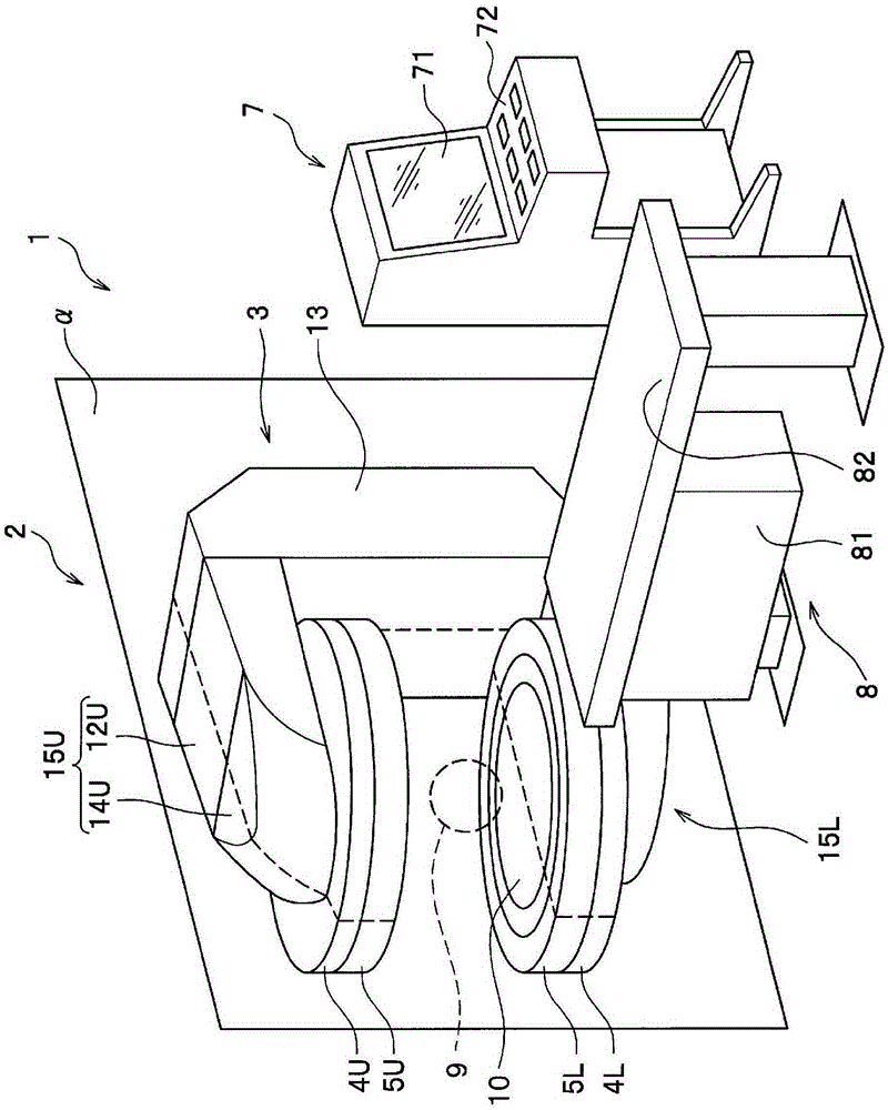
[0046] figure 1 A perspective view of a magnetic resonance imaging apparatus (MRI apparatus) 1 according to a first embodiment of the present invention is shown. The MRI apparatus 1 has: a magnet device 2 that generates a static magnetic field with uniform magnetic field strength in the imaging space 9; a bed 8 that transports the subject to the imaging space 9 in a supine state; and a magnet device 2, the bed 8, etc. The entire MRI apparatus 1 is controlled, and the control unit 7 acquires images representing the physical and chemical properties of the subject by utilizing the nuclear magnetic resonance phenomenon generated when the subject is irradiated with high-frequency pulses.

[0047]The control unit 7 is connected to the magnet device 2, the bed 8, and the like. The control unit 7 has an operation unit 72 that can be operated by an operator to adjust the control content thereof, and a display unit 71 that displays an acquired image. The operation unit 72 accepts oper...

no. 2 approach

[0064] Figure 9 A perspective view showing the upper half of the yoke 3 of the magnet device according to the second embodiment of the present invention. The point of difference between the second embodiment and the first embodiment lies in the shape of the yoke 3, among them the shape of the horizontal front end portion 14U of the yoke. The outer surface 15e of the horizontal front end portion 14U of the yoke in the first embodiment is formed using a curved surface, whereas the outer surface 15e of the horizontal front end portion 14U of the yoke in the second embodiment is formed using a plurality of inclined surfaces with different inclination angles.

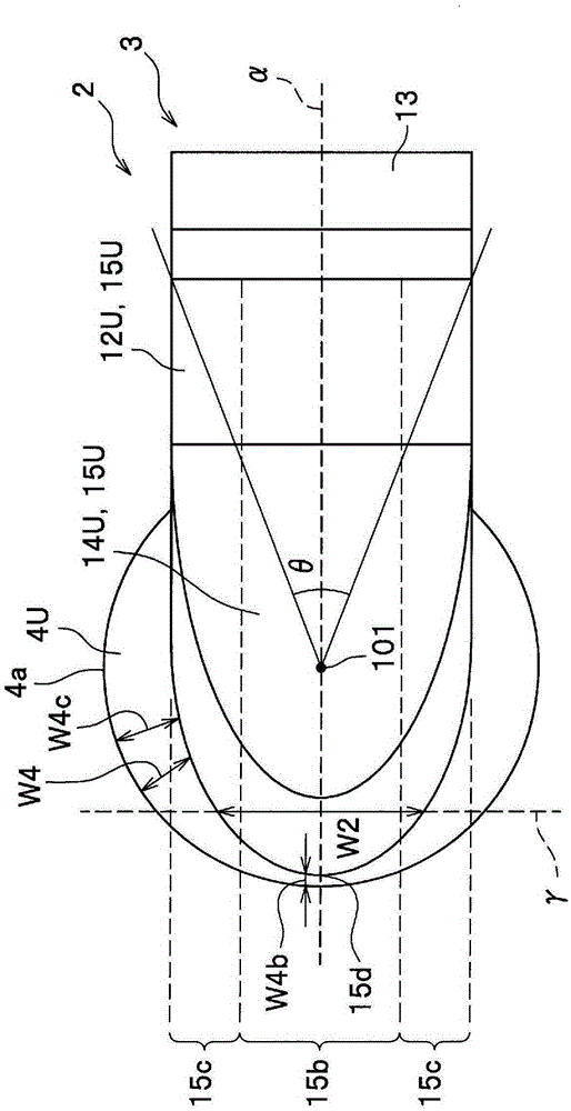
[0065] Figure 10A plan view of a magnet device 2 according to a second embodiment of the present invention is shown. The horizontal front end portion 14U of the yoke has a tapered shape. Specifically, the width W2 in the normal direction of the vertical symmetry plane α decreases in two stages as it approaches the front...

no. 3 approach

[0071] Figure 13 A perspective view showing the upper half of the yoke 3 of the magnet device according to the third embodiment of the present invention. The difference between the third embodiment and the second embodiment lies in the shape of the yoke 3 , which is also the shape of the yoke vertical portion 13 . In the second embodiment, the yoke vertical portion 13 is one column, while in the third embodiment it is a plurality of columns (in Figure 13 2 in the example). Accordingly, a pipe connecting the coil storage containers 5U and 5L, wiring connecting the superconducting coils 6U and 6L, a refrigerator, and the like can be provided between the plurality of adjacent yoke vertical portions 13 . By arranging pipes, wiring, and the like in the area between adjacent yoke vertical portions, the area through which the bed 8 passes can be enlarged and the degree of freedom of movement of the bed 8 can be ensured more widely. In addition, by providing a refrigerator betwee...


PUM


Abstract

This magnet device (2) is provided with a pair of generally disk-shaped magnetic poles (4U) situated in opposition, and a yoke (3) which is C-shaped or U-shaped in side view and which is situated with either end of the C-shape or U-shape situated in proximity to the magnetic poles (4U). The yoke (3) has a yoke-side opposing portion (15U) in proximity to and opposing the magnetic poles (4U), the yoke-side opposing portion (15U) having a center strip area (15b) that includes part of a vertical symmetric plane (alpha) of the yoke (3), and side strip areas (15c) situated to either side of the center strip area (15b), further away from the vertical symmetric plane (alpha). At a height (W3) of the yoke-side opposing portion (15U) with respect to a yoke-side opposing surface (15a) which is situated in proximity and opposing the magnetic poles (4U), the center strip area (15c, W3b) is taller than the side strip areas (15c, W3c). The height (W3) of the yoke-side opposing portion (15U) with respect to the yoke-side opposing surface (15a) decreases in weakly monotonic fashion further away from the vertical symmetric plane (alpha), and the maximum value and minimum value thereof differ.

Description

technical field [0001] The present invention relates to a magnet device and a magnetic resonance imaging device (hereinafter referred to as an MRI (Magnetic Resonance Imaging: magnetic resonance imaging) device) including the magnet device. Background technique [0002] The MRI device places the subject in an imaging space formed with a uniform static magnetic field, and uses the nuclear magnetic resonance phenomenon generated when the subject is irradiated with high-frequency pulses to obtain images representing the physical and chemical properties of the subject. Also, the image is mainly used for medical purposes. The MRI apparatus is roughly classified into a horizontal type in which the direction of the static magnetic field is oriented horizontally, and a vertical type in which the direction is oriented vertically. In the former, that is, the horizontal type MRI apparatus, the imaging space is in a tunnel penetrating in the horizontal direction, and the subject enters...

Claims


Application Information

Patent Timeline
Patent Type & Authority Applications(China)
IPC IPC(8): A61B5/055G01R33/381
CPCG01R33/3806A61B5/055G01R33/3815
Inventor 堀知新阿部充志
Owner HITACHI HEALTHCARE MFG LTD
Why Eureka
Try Eureka