Image distorting correction apparatus

A technology for correcting device and image distortion, applied in electrode devices and related components, image communication, television, etc., can solve the problems of leakage magnetic field, increase in cost, increase in power consumption, etc., and achieve the effect of reducing mutual inductance and cost.

Inactive Publication Date: 2005-08-31
MITSUBISHI ELECTRIC CORP
View PDF1 Cites 0 Cited by
  • Summary
  • Abstract
  • Description
  • Claims
  • Application Information

AI Technical Summary

Problems solved by technology

[0035] Existing image distortion correction circuits such as Figure 24 As shown, in order to realize the core 13 of the intermediate pincushion distortion correction saturable reactor unit 10, three partial cores 13a to 13c are used, so the cost increases and the manufacturing method becomes complicated.
[0036] Moreover, since the entire system including the iron core 13 and the magnets 11 and 12 is not a closed magnetic circuit, a low-intensity leakage magnetic field is generated, and the vertical correction coil is rectified by a diode, so there is a problem that the vertical deflection sensitivity is deteriorated due to the resistance component of the diode. , at the same time, problems such as increased power consumption

Method used


Image

  • Image distorting correction apparatus
  • Image distorting correction apparatus
  • Image distorting correction apparatus

Examples


Embodiment 1

[0091]

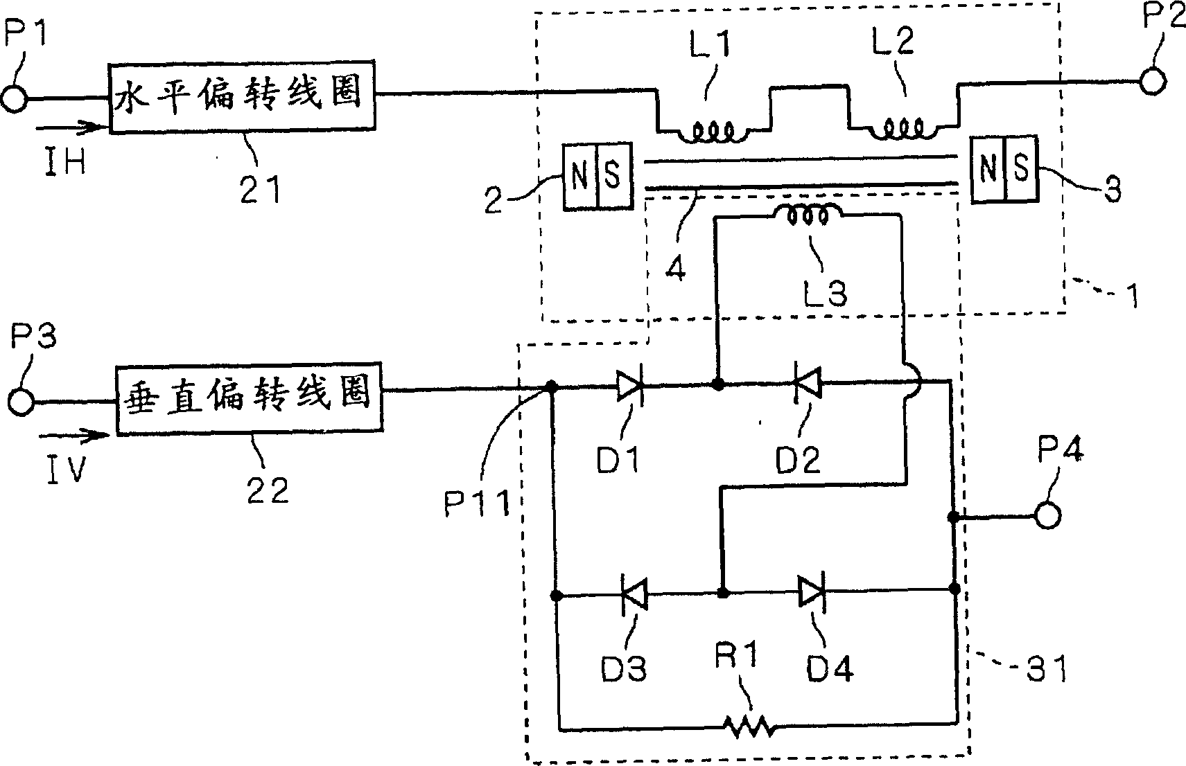
[0092] figure 1 It is a circuit diagram showing the circuit configuration of the image distortion correction device according to the first embodiment of the present invention. exist figure 1 Among them, 1 is the middle pincushion distortion correction saturable reactor unit, 2 and 3 are magnets, and 4 is an iron core.

[0093] As shown in the figure, the horizontal deflection current IH flows through the horizontal deflection current path between the terminal P1 and the terminal P2, and the horizontal deflection coil 21, the horizontal correction coil L1 and the horizontal correction coil are connected in series between the terminals P1 and P2. L2. The horizontal correction coil L1 and the horizontal correction coil L2 are respectively wound on the iron core 4 .

[0094] On the other hand, the vertical deflection current IV flows through the vertical deflection current path between the terminal P3 and the terminal P4, and the vertical deflection coil 22 is prov...

Embodiment 2

[0126] Figure 12 is a cross-sectional view showing the structure of the middle pincushion distortion correcting saturable reactor unit in the image distortion correcting apparatus according to Embodiment 2 of the present invention. circuit configuration and figure 1 The image distortion correction circuit of the shown embodiment 1 has the same circuit configuration.

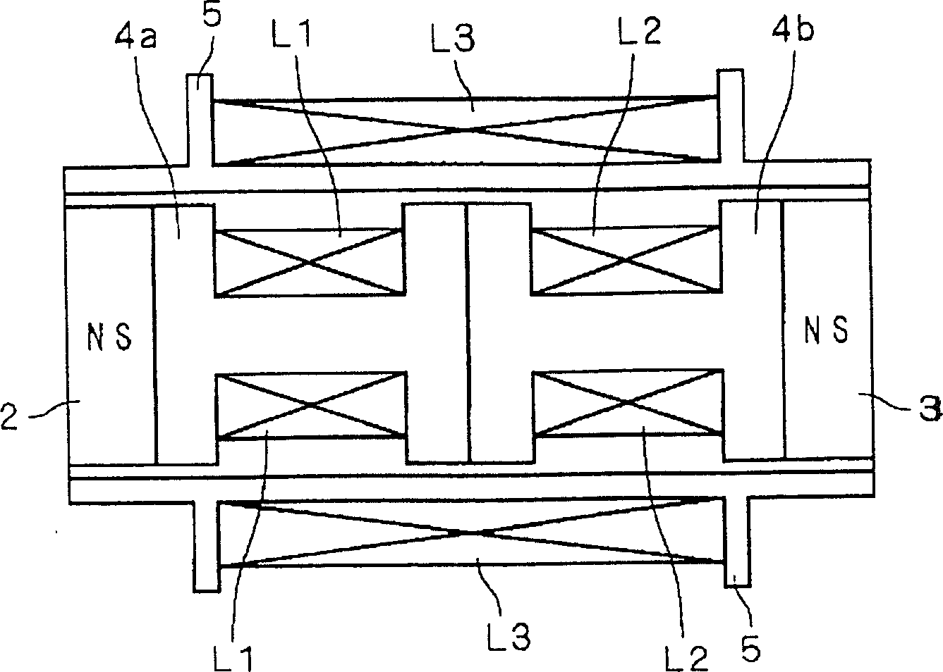
[0127] As shown in the figure, figure 1 The iron core 4 is realized by an integrally formed one-unit iron core 6. Further, a horizontal correction coil L1 is wound in a region of the core 6 on the magnet 2 side, and a horizontal correction coil L2 is wound in a region on the magnet 3 side. Other composition and figure 2 Example 1 shown is the same.

[0128] The image distortion correction device of the second embodiment configured in this way can perform the same operation as the image distortion correction device of the first embodiment. Furthermore, with the configuration of Embodiment 2, compared wit...

Embodiment 4

[0135] 14 is a cross-sectional view showing the structure of an intermediate pincushion distortion correction saturable reactor unit in an image distortion correction apparatus according to Embodiment 4 of the present invention. Moreover, the circuit configuration is the same as figure 1 The image distortion correction circuit of the shown embodiment 1 has the same circuit configuration.

[0136] As shown in the figure, a substantially U-shaped yoke plate 9 is further provided outside a part of the bobbin 5 as a closed magnetic circuit member. The yoke plate 9 is made up of cheap materials such as silicon steel sheets, and its two end faces are closely connected to the end faces of the magnets 2 and 3 on the left and right sides respectively, and the iron core 6-magnet 2,3-yoke plate 9 forms a closed magnet as a whole. road. Moreover, other components are related to Figure 12 Example 2 shown is the same.

[0137] Also, the yoke plate 9 may be provided on the intermediate...


PUM


Abstract

An image distortion correcting device with reduced cost and reduced consumption power is provided. Horizontal correction coils (L1) and (L2) are wound around partial cores (4a) and (4b). The two horizontal correction coils (L1) and (L2) are wound in such winding directions that they produce magnetic fields in opposite directions. A bobbin (5) having an insulating property covers the partial cores (4a) and (4b) and magnets (2) and (3) in the winding direction of the horizontal correction coils (L1) and (L2), and a vertical correction coil (L3) is wound on the bobbin (5) around the partial cores (4a) and (4b) along the windings of the horizontal correction coils (L1) and (L2). That is to say, the vertical correction coil (L3) is wound over the horizontal correction coils (L1) and (L2) along the periphery of their windings with the bobbin (5) interposed therebetween. This vertical correction coil (L3) is wound in such a direction that it produces a magnetic field directed to cancel the bias magnetic field produced by the magnets (2) and (3).

Description

technical field [0001] The present invention relates to an image distortion correction device for a CRT (cathode ray tube) display device. Background technique [0002] <Pincushion distortion in the middle of vertical lines> [0003] Figure 18 It is a schematic diagram showing the pincushion distortion in the middle part of the vertical line (hereinafter referred to as "middle pincushion distortion") that has repeatedly become a problem in the CRT display device used in the current high-quality display monitor. In this figure, a vertical line 23 is shown on the peripheral portion of the screen (screen) 20, and a vertical line 24 in the middle portion is shown in the middle portion of the screen (the middle portion between the center portion of the screen and the peripheral portion). When the vertical line 23 of the center portion is approximately linear, the state in which the vertical line 24 of the middle portion is distorted into a pincushion shape is called inter...

Claims


Application Information

Patent Timeline
Patent Type & Authority Patents(China)
IPC IPC(8): H04N3/23H01J29/70H01J29/76H04N3/237
CPCH01J2229/5687H01J29/705H04N3/23
Inventor 宫本佳典安井裕信瓶子晃永石森彰西野浩章
Owner MITSUBISHI ELECTRIC CORP
Why Eureka
Try Eureka