Biomechanics measuring device for spinal column in vivo

A biomechanical and measuring device technology, applied in the field of medical devices, can solve the problems of unable to use spine biomechanical research, unable to test and study in vivo spine biomechanics, unable to accurately obtain the magnitude of loading stress, etc.

Inactive Publication Date: 2016-01-06
SECOND MILITARY MEDICAL UNIV OF THE PEOPLES LIBERATION ARMY
View PDF9 Cites 5 Cited by
  • Summary
  • Abstract
  • Description
  • Claims
  • Application Information

AI Technical Summary

Problems solved by technology

Neither of these two methods can be used for in vivo spine biomechanical testing and research on living people
[0004] At present, the Chinese patent "a scoliosis traction pushing bed" (CN101606871) by Li Ming et al., the invention patent aims at evaluating the flexibility of scoliosis by traction and pushing. The defect of this patent is that it cannot be accurately obtained The magnitude of the loading stress, while the results are only qualitative, the device cannot be used for quantitative spinal biomechanical studies

Method used


Image

  • Biomechanics measuring device for spinal column in vivo
  • Biomechanics measuring device for spinal column in vivo
  • Biomechanics measuring device for spinal column in vivo

Examples


Embodiment 1

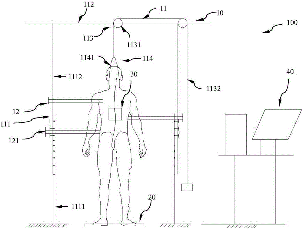
[0028] figure 1 Schematic diagram of the structure of the in vivo biomechanical measurement device for the spine of Example 1 when the spinal submandibular traction is stretched

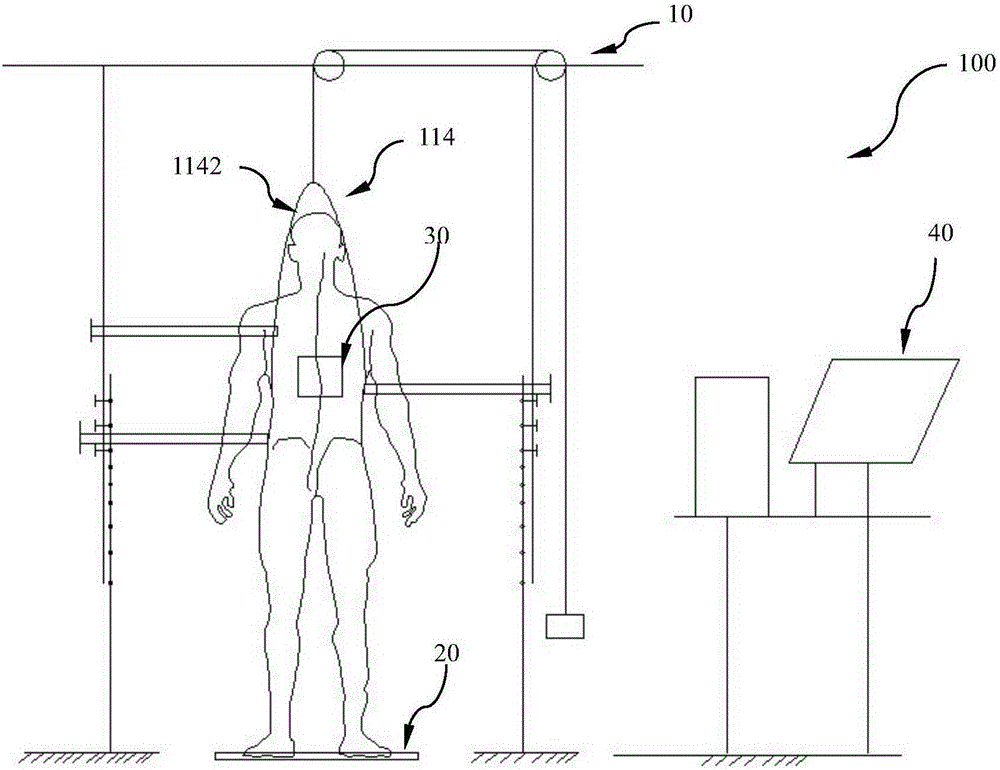
[0029] figure 2 Schematic diagram of the structure when the in vivo biomechanical measuring device for the spine of Example 1 is used for traction and stretching of the spine underarm

[0030] image 3 Schematic diagram of the structure when the rigid loading frame is pressed down for the spine in vivo biomechanical measurement device of embodiment 1

[0031] right figure 2 , 3, 4 and figure 1 The same part is not explained.

[0032] Such as figure 1 , as shown in 2 and 3, the spinal column in vivo biomechanical measurement device 100 includes a stress loading part 10, a force measuring part 20, located below the stress loading part 10, and a spine shape measuring part 30, which is movably arranged on the subject's spine Afterwards, the data processing unit 40 is connected with the force mea...

Embodiment 2

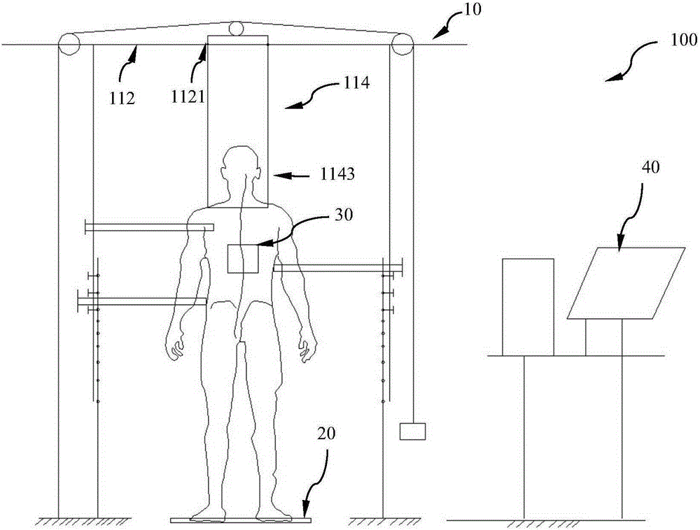
[0052] Figure 4 Schematic diagram of the structure when the in vivo biomechanical measurement device for the spine of Example 2 is used for spinal submandibular traction and stretching

[0053] as such figure 1 , 2, 3 A simplification of the gate-shaped structure. The gate-shaped structure composed of a beam and two columns is changed into an Arabic numeral "7" composed of a beam and a column. The corresponding ropes should be arranged as shown in Figure 4 As shown, another pulley is arranged at the end of the crossbeam. As an adaptation, the end of the pusher 122 in the middle of the three pushers 121 that is close to the subject is correspondingly designed as a hook, so as to The subject's waist can be pushed forward and pulled horizontally, and the other pushing piece can also be designed as a hook like the one in the middle. Other operations are similar to Example 1.

[0054] Effects and beneficial effects of the embodiment

[0055] The in vivo biomechanical measureme...


PUM


Abstract

A biomechanics measuring device for a spinal column in vivo is used for measuring and researching biomechanics of a human spinal column in vivo. The biomechanics measuring device is characterized by comprising a stress applying portion used for applying stress loads to a human spinal column in different directions, an applied force measuring portion arranged under the stress applying portion and used for carrying a testee and measuring applied forces to the testee, a spinal column state measuring portion movably arranged to the back of the testee and used for measuring spinal column states of the testee, and a data processing portion used for receiving signals acquired by the applied force measuring portion and the spinal column measuring portion to analyze. The stress applying portion comprises a vertical applying unit and a horizontal applying unit, the vertical applying unit is used for stretching or pressing down the testee in the vertical direction, and the horizontal stress applying unit is used for applying to the testee's body to distort the testee's spinal column.

Description

technical field [0001] The invention belongs to the technical field of medical devices, and in particular relates to an in vivo biomechanical measurement device for the spine. Background technique [0002] The study of spinal biomechanics is the theoretical basis of spinal internal fixation, spinal external fixation brace and spinal motor rehabilitation. The current research on spine biomechanics mainly uses three-dimensional finite element models and cadaver models, and the relevant data obtained from these two models cannot fully fit the biomechanical responses of living spines. In vivo biomechanical research can obtain real-time responses of the body to spinal loads. Currently, with the development and application of SpineScan and Spinemouse (both methods of spine measurement, spine scanning technology), the curves of the sagittal and coronal planes of the whole spine and the relative sagittal planes of two adjacent vertebral bodies can be measured in real time. The inc...

Claims


Application Information

Patent Timeline
Patent Type & Authority Applications(China)
IPC IPC(8): A61B5/22A61B5/107A61B5/00
Inventor 杨长伟赵检陈园园李明
Owner SECOND MILITARY MEDICAL UNIV OF THE PEOPLES LIBERATION ARMY
Why Eureka
Try Eureka