
A guiding ladder for an oil storage tank cleaning robot to enter and exit the tank wall manhole

A technology for cleaning robots and oil storage tanks, applied in the field of guide ladders, can solve problems such as corrosion, affecting the accuracy of oil calculation, electrostatic accidents, etc., and achieve the effects of convenient operation, simple structure, convenient disassembly and transportation

Active Publication Date: 2017-08-04
BEIJING INSTITUTE OF PETROCHEMICAL TECHNOLOGY
View PDF10 Cites 0 Cited by
  • Summary
  • Abstract
  • Description
  • Claims
  • Application Information

AI Technical Summary

Problems solved by technology

Impurities and moisture will reduce the quality of refined oil and affect the accuracy of oil product calculation; accelerate the corrosion of oil tanks, and in severe cases will cause perforation of the bottom plate, resulting in oil leakage accidents; generate and accumulate static electricity, resulting in static electricity accidents
In addition, when oil products are upgraded or replaced with different oil products, the remaining oil products in the tank and the newly loaded oil products cannot be mixed. When the oil tank leaks or is damaged in other ways, when inspection or hot repair is required, the oil must be inspected. Tanks are cleaned, and oil storage tanks must also be cleaned and repaired regularly according to national regulations

Method used


Image

  • A guiding ladder for an oil storage tank cleaning robot to enter and exit the tank wall manhole
  • A guiding ladder for an oil storage tank cleaning robot to enter and exit the tank wall manhole
  • A guiding ladder for an oil storage tank cleaning robot to enter and exit the tank wall manhole

Examples


Embodiment Construction

[0034] The following clearly and completely describes the technical solutions in the embodiments of the present invention. Obviously, the described embodiments are only some of the embodiments of the present invention, but not all of them. Based on the embodiments of the present invention, all other embodiments obtained by persons of ordinary skill in the art without making creative efforts belong to the protection scope of the present invention.

[0035] The guide ladder of the present invention will be further described below in conjunction with specific embodiments.

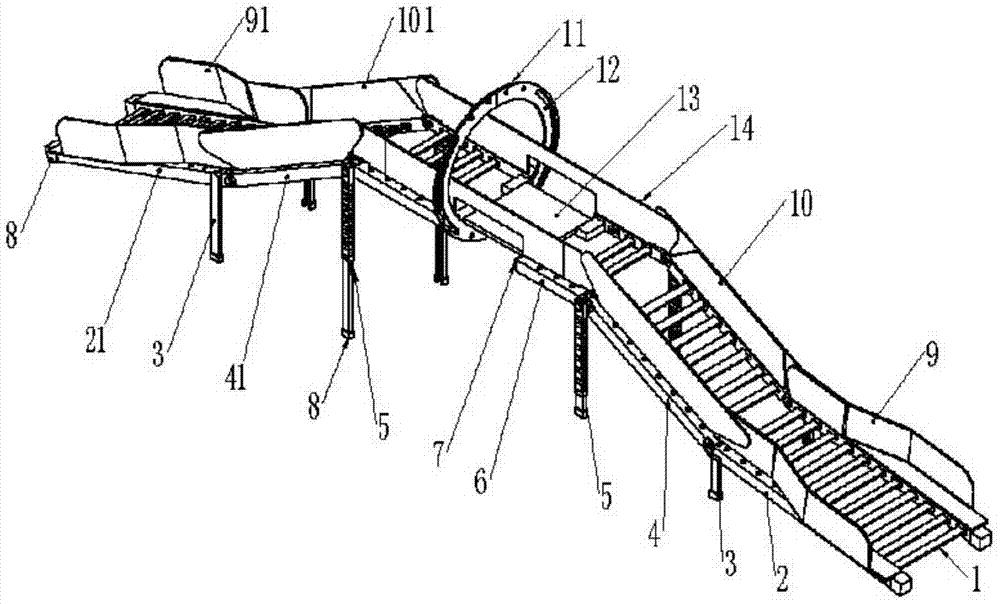
[0036] Such as Figure 1 to Figure 6 As shown, this embodiment provides a guide ladder for an oil storage tank cleaning robot to enter and exit the tank wall manhole, including: a main body frame, telescopic legs, fixed legs, flanges, limit plates, pedals, connecting rods, pads and protective pads. The main frame includes five parts: the first ladder, the second ladder, the third ladder, the fourth ladder and...


PUM


Abstract

The invention discloses a shell manhole guide ladder for an oil storage tank cleaning robot to get in or out. The guide ladder comprises a body frame, telescopic legs, fixed legs, a flange, limiting plates, a pedal, connecting rods, protection pads and protection feet. The body frame is composed of five parts, all the parts are connected in a hinged mode, and each part is a parallelogram mechanism formed by hinging the connecting rods; the telescopic legs are hinged to a third ladder body of the body frame and are each provided with a locking mechanism; the fixed legs are welded to one end of the outer side of a first ladder body of the body frame; the flange is welded to the middle vertical face of the third ladder body of the body frame; the limiting plates are symmetrically welded to the upper portions of all the parts of the body frame; the pedal is horizontally installed in the middle of the third ladder body of the body frame; the protection pads are installed on the fixed face of the flange and one side of the middle of the third ladder body of the body frame; the protection feet are installed at the bottom of the body frame. The height, the position and the shape of the guide ladder can be flexibly adjusted, and the guide ladder is convenient to use and operate. The shell manhole guide ladder is installed in a shell manhole of a large vertical inner floating roof oil storage tank and is capable of accurately guiding the robot to get in or out of the oil storage tank.

Description

technical field [0001] The invention relates to the field of equipment for cleaning oil storage tanks, in particular to a guide ladder installed in a tank wall manhole of a large vertical inner floating roof oil storage tank to guide an oil tank cleaning robot into and out of the tank wall manhole. Background technique [0002] Utilizing storage tanks for storage is the main way of strategic petroleum reserves. During the long-term storage and transportation of refined oil tanks, a small amount of sand, soil, heavy metal salts and other impurities in the refined oil will settle and accumulate at the bottom of the oil tank together with water due to the density difference, forming a black and thick gelatinous substance. That is, the bottom mud of the oil tank. Impurities and moisture will reduce the quality of refined oil and affect the accuracy of oil product calculation; accelerate the corrosion of oil tanks, and in severe cases will cause perforation of the bottom plate, ...

Claims


Application Information

Patent Timeline
Patent Type & Authority Patents(China)
IPC IPC(8): B08B13/00
CPCB08B13/00
Inventor 代峰燕郑霄峰李冬冬陈家庆高庆珊邢爽
Owner BEIJING INSTITUTE OF PETROCHEMICAL TECHNOLOGY
Learn More