Bending machine and method of use thereof

A technology of bending machine and frame, which is applied in the field of bending machine, can solve the problems of large size of driving cylinder and high requirement of driving pressure, and achieve the effect of convenient installation

Inactive Publication Date: 2017-10-13
安徽省华夏机床制造有限公司
View PDF2 Cites 0 Cited by
  • Summary
  • Abstract
  • Description
  • Claims
  • Application Information

AI Technical Summary

Problems solved by technology

[0007] Aiming at the problems of the above-mentioned large driving cylinder size and high driving pressure requirements in the existing bending machine, the present invention provides a bending machine and its use method, which utilizes the principle of leverage and uses a smaller size oil cylinder to generate higher pressure. The bending pressure reduces the use cost of the oil cylinder, and also reduces the driving pressure requirements of the power components, thereby greatly reducing the manufacturing cost of the bending machine

Method used


Image

  • Bending machine and method of use thereof
  • Bending machine and method of use thereof
  • Bending machine and method of use thereof

Examples


Embodiment 1

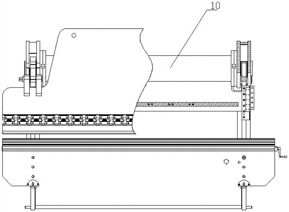
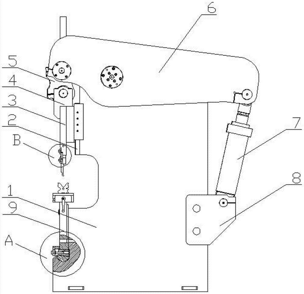
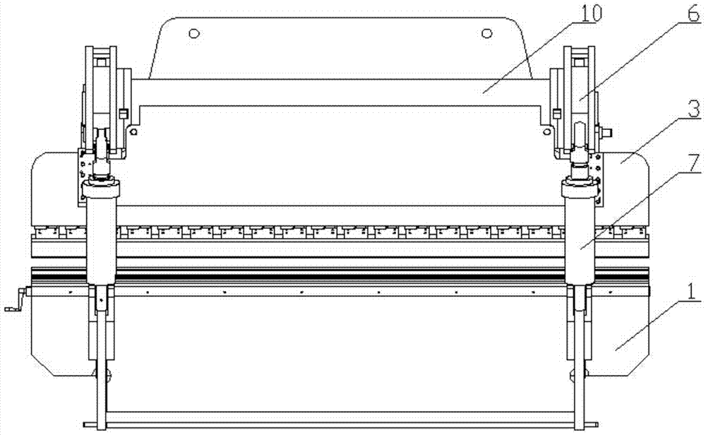
[0056] Such as figure 1 , figure 2 and image 3 As shown, a bending machine includes a frame 1, a slider guide rail 2 arranged on one side of the frame 1, a slider 3 arranged on the slider guide rail 2 and a power assembly, and also includes a synchronous shaft 10; the power assembly It is divided into two groups, which are symmetrically arranged on the frame 1 respectively. Each group of power components includes an oil cylinder seat 8 arranged on the opposite side of the slider 3 on the frame 1, a beam arm 6 arranged on the top of the frame 1 through a pin connection, and Connect the cylinder base 8 and the oil cylinder 7 at one end of the beam arm 6 through a pin; the opposite end connected to the oil cylinder 7 on the beam arm 6 is connected with a straightening connecting rod 5 through a pin; one end of the straightening connecting rod 5 is connected through a pin. There are two slider guide rods 4; the two slider guide rods 4 are fixedly connected with the slider 3; t...


PUM


Abstract

The invention discloses a bending machine, which belongs to the field of bending equipment for metal plates, and solves the problems of large driving oil cylinder specifications and high driving pressure requirements in the existing bending machine. The device of the present invention comprises a frame, a slider guide rail, a slider and a power assembly, and also includes a synchronous shaft; The oil cylinder base on the opposite side, the beam arm arranged on the top of the frame through the pin shaft connection, and the oil cylinder connected with the oil cylinder base and one end of the beam arm through the pin shaft; rod; one end of the straightening connecting rod is connected with two slider guide rods through a pin shaft; the two slider guide rods are fixedly connected with the slider; the beam arms in the two groups of power assemblies are connected through a synchronous shaft. The invention can reduce the use cost of the oil cylinder and the driving pressure requirement of the power element, thereby greatly reducing the manufacturing cost of the bending machine.

Description

technical field [0001] The invention belongs to the field of sheet metal bending equipment, and more specifically relates to a bending machine and a method for using the same. Background technique [0002] The bending machine is a machine capable of bending thin plates. Its structure mainly includes a bracket, a workbench and a clamping plate. The workbench is placed on the bracket. The workbench is composed of a base and a pressure plate. The base is composed of a seat shell, a coil and a cover plate, the coil is placed in the depression of the seat shell, and the top of the depression is covered with a cover plate. When in use, the wire is energized to the coil, and after energization, an attractive force is generated on the pressure plate, so as to realize the clamping of the thin plate between the pressure plate and the base. Due to the use of electromagnetic force clamping, the pressure plate can be made into a variety of workpiece requirements, and the workpiece with ...

Claims


Application Information

Patent Timeline
Patent Type & Authority Patents(China)
IPC IPC(8): B21D5/06
Inventor 费文彪
Owner 安徽省华夏机床制造有限公司
Why Eureka
Try Eureka