Bending die assembly, bending die kneading assembly, bending machine and bending method

A technology of mold assembly and buckling machine, which is applied in the field of buckling mold assembly, and can solve problems such as poor koji making effect and poor pulp extraction effect

Pending Publication Date: 2021-07-30
宜宾智特机械有限公司
View PDF2 Cites 0 Cited by
  • Summary
  • Abstract
  • Description
  • Claims
  • Application Information

AI Technical Summary

Problems solved by technology

[0005] The object of the present invention is to provide a buckling die assembly, a buckling die kneading assembly, a buckling machine and a buckling method, which solves the problems of the existing buckling machine compared with manual bending. Poor, poor pulp extraction effect and other technical problems

Method used


Image

  • Bending die assembly, bending die kneading assembly, bending machine and bending method
  • Bending die assembly, bending die kneading assembly, bending machine and bending method
  • Bending die assembly, bending die kneading assembly, bending machine and bending method

Examples


Embodiment 1

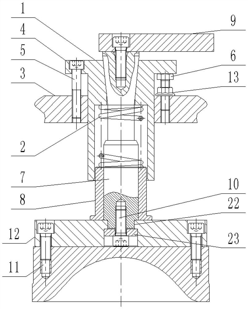
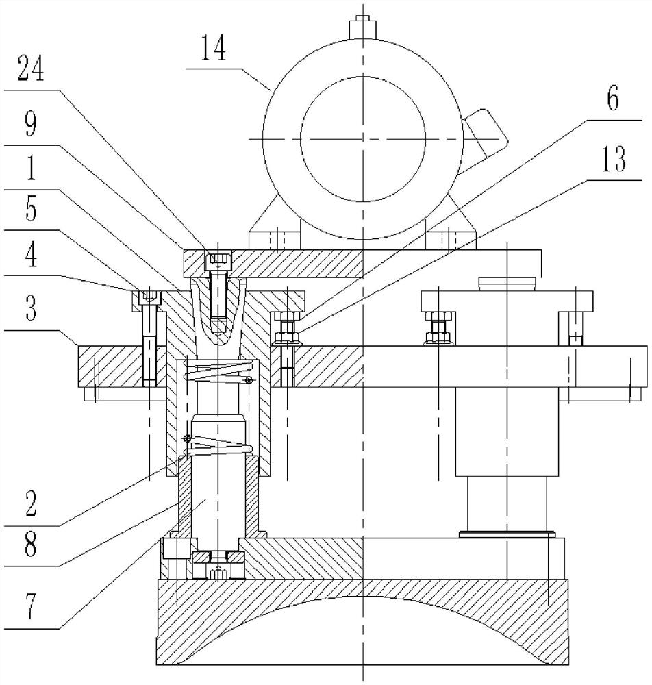
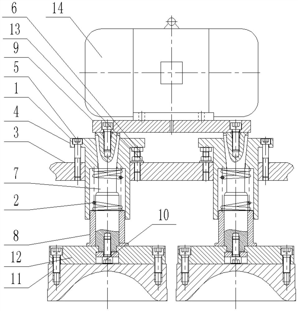
[0057] Such as figure 1 As shown, a die handle assembly of the present invention includes a die handle cover 1, a die handle that is slidably installed in the die handle cover 1 and abuts against the upper side of the inner hole of the die handle cover 1 through a spring 2, and the die handle cover 1 The joint with the mold shank is a conical fit structure, and as the spring 2 is compressed, the mold shank sleeve 1 and the mold shank are separated from the joint at the conical fit.

[0058] During use, the vibrating power source drives the mold handle, and the mold handle cover 1 is fixed on the piston rod of the oil cylinder used for pressing the die, and the bottom of the die handle is the die. When buckling, the piston rod of the oil cylinder is extended, so that the die is located in the chain box, and the bent material in the chain case is pressed and formed; at the same time, the piston rod continues to extend, the die and the handle cannot move down, and the handle cove...

Embodiment 2

[0062] In order to ensure the precise alignment between the die and the inner cavity of the chain box, it is necessary to ensure the perpendicularity of the axis of the mold handle to the bottom molding surface of the crank block; and to ensure the perpendicularity of the axis of the mold handle to the bottom molding surface of the crank block, it is necessary to ensure The verticality of the axis of the mold shank 1 attached to the mold shank relative to the bottom molding surface of the crank block. Therefore, in this embodiment, it is necessary to carry out a scheme optimization description on how to adjust the mold handle sleeve to obtain better verticality.

[0063] Such as figure 1 As shown, in the present invention, on the basis of Embodiment 1, the circumference of the outer wall of the mold shank 1 protrudes outward to form an eversion edge 4, and the eversion edge 4 is threadedly connected to the bearing surface by a plurality of fastening screws 5 3, and a pluralit...

Embodiment 3

[0069] The specific implementation structure about the mold handle is as follows:

[0070] Such as figure 1 As shown, the mold handle includes a handle core 7 and a limit sleeve 8 sleeved on the handle core 7, the spring 2 is sleeved on the handle core 7, and its two ends are respectively connected to the upper side of the inner hole of the mold handle sleeve 1. And the upper side of the limit sleeve 8 abuts, and the limit sleeve 8 is matched with the inner hole of the mold handle cover 1, and a section of the outer peripheral surface of the handle core 7 is matched with a section of the hole wall cone of the limit sleeve 8 inner hole.

[0071] Preferably, the shank 7 includes a coaxial and sequentially connected equal-diameter matching section, an equal-diameter transition section, and a conical conical fit with the limiting sleeve 8. The inner hole of the limiting sleeve 8 includes The tapered holes that are coaxial and sequentially connected with the circular frustum secti...


PUM


Abstract

The invention discloses a bending die assembly, a bending die kneading assembly, a bending machine and a bending method. The bending machine comprises a bending die kneading assembly for pressing and forming a bending material in a chain box. The bending die kneading assembly comprises a stand column, a guide support slidably installed on the stand column and the bending die assembly fixed to the bearing face of the guide support. The bending die assembly comprises a die handle assembly, a pressing die fixed on a die handle of the die handle assembly and a vibration power source for applying vibration to the pressing die. The die handle assembly comprises a die handle sleeve and a die handle which is slidably mounted in the die handle sleeve and abuts against the upper side of an inner hole of the die handle sleeve through a spring, wherein the part where the die handle sleeve and the die handle are attached to each other is of a conical matching structure. The device has the advantages that automatic starter propagation is realized through mechanical equipment, the working efficiency is improved, the labor intensity of workers is reduced, and the labor cost is reduced, and meanwhile, 'manual starter treading' can be restored relatively well, so that a sufficient pulp extraction effect like manual starter treading and a starter block which is tight in appearance, loose in middle and convenient to ferment are obtained.

Description

technical field [0001] The invention relates to the technical field of wine making, in particular to a buckling die assembly, a buckling die kneading assembly, a buckling machine and a buckling method. Background technique [0002] In the production process of liquor, the koji material needs to be pressed into koji blocks. And the production process of the koji and the quality of the koji affect the quality and the style of the wine to a large extent, especially famous and high-quality liquor, which has higher requirements for the production of the koji. In order to improve the pressing efficiency and pressing quality of koji, a variety of automatic pressing equipment for koji has been designed. In order to improve pressing efficiency and automation, a buckling machine has been designed, such as a buckling machine for continuous stepping and forming disclosed in the prior art CN101857828B, which includes a frame, and a transmission frame fixed on the frame. The chain box t...

Claims


Application Information

Patent Timeline
IPC IPC(8): B30B11/14B30B11/02B30B15/00B30B15/02F16H7/06F16H57/028F16H57/035F16G13/06F16G15/12
CPCB30B11/027B30B11/14B30B15/0005B30B15/02F16G13/06F16G15/12F16H7/06F16H57/028F16H57/035
Inventor 舒代根刘强孙银楷
Owner 宜宾智特机械有限公司
Why Eureka
Try Eureka