Drill bit

A drill bit and drill body technology, which is applied in the direction of drill repair, drill tool accessories, drilling/drilling equipment, etc., can solve the problems of debris reducing the chip removal capacity of the drill bit, reducing the service life of the drill bit, and the drill tip is prone to high temperature, etc. Achieve the effect of obvious guiding effect, increase the adhesion area, and easy processing

Active Publication Date: 2016-01-06
乐清市天中天五金工具有限公司
View PDF6 Cites 0 Cited by
  • Summary
  • Abstract
  • Description
  • Claims
  • Application Information

AI Technical Summary

Problems solved by technology

Since the debris will hit the right side wall of the spiral chip guide groove during the movement, it will generate a recoil force on the debris and affect the trajectory of the debris, which will greatly reduce the chip removal ability of the drill bit; and the operating sp

Method used


Image

  • Drill bit
  • Drill bit
  • Drill bit

Examples


Embodiment 1

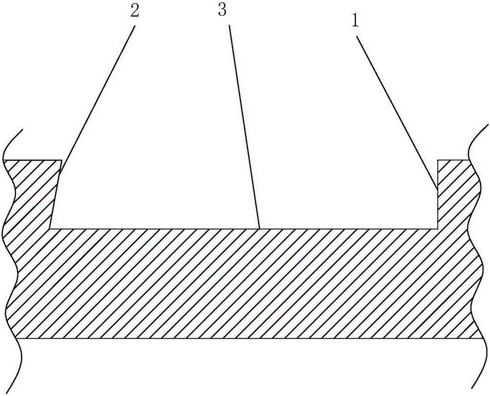
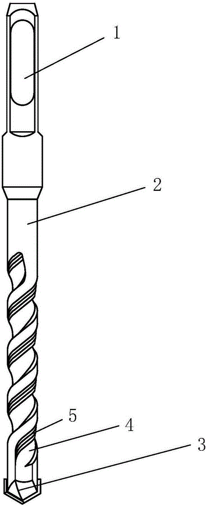
[0025] Refer to attached Figure 2-3 As shown, a drill bit includes a drill shank 1, a drill body 2 and a drill tip 3, a helical chip guide 4 is provided on the drill body, and a concave arc surface 9 is formed on the left side wall of the helical chip guide 4.

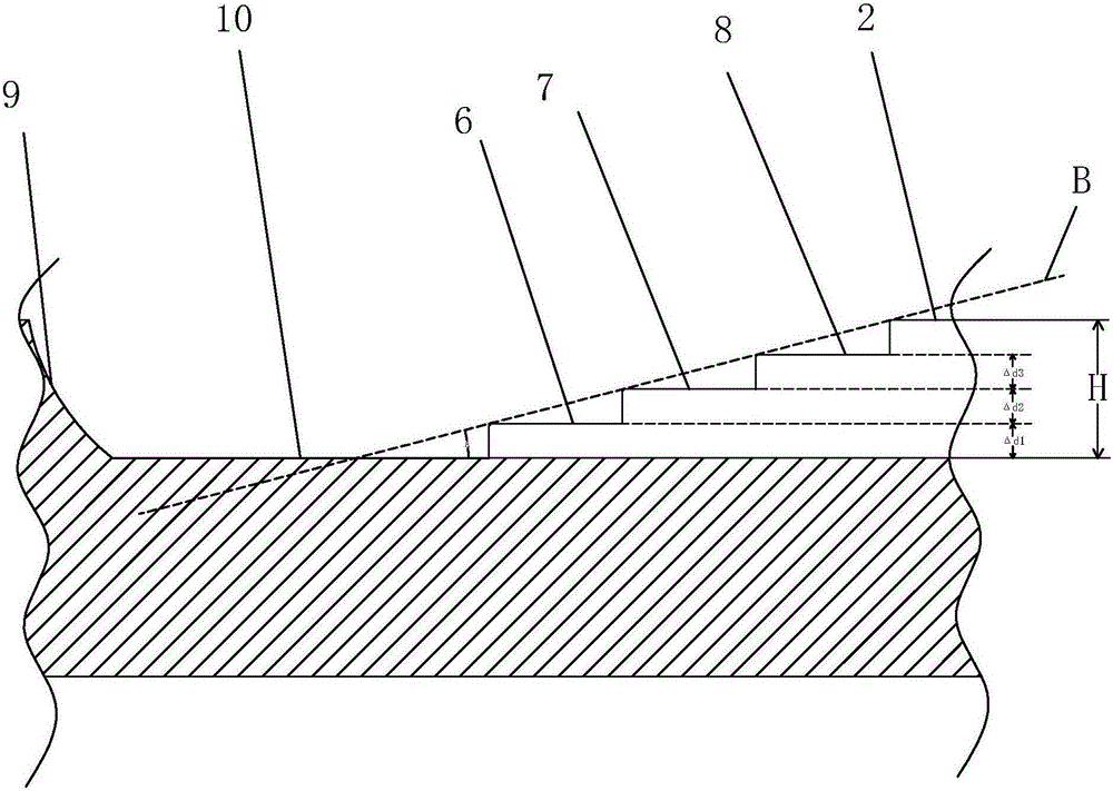
[0026] On the bottom surface 10 of the spiral chip guide, there is a chip guide portion 5 formed by flange I6, flange II7 and flange III8. The left side wall of flange I6 coincides with the spiral center line of the spiral chip guide groove 4, the right side wall of flange I6 coincides with the left side wall of flange II7, and the right side wall of flange II7 coincides with the left side of flange III8 The walls coincide, and the left side wall of the flange III8 coincides with the right side wall of the spiral chip guide groove 4. The flange I6 , flange II7 and flange III8 extend from the starting position of the spiral chip guide 4 along the direction of the spiral chip guide 4 to the end position of the spiral c...


PUM


Abstract

The invention discloses a drill bit which comprises a drill handle, a drill body and a drill tip. The drill body is provided with a spiral scrap guide groove. A scrap guide portion is arranged on the bottom face of the spiral scrap guide groove and extends from the initial position of the spiral scrap guide groove to the terminal position of the spiral scrap guide groove along the spiral scrap guide groove. The left side of the scrap guide portion is close to the spiral center line of the spiral scrap guide groove. The right side of the scrap guide portion is attached to the right side wall of the spiral scrap guide groove. The scrap guide portion is composed of at least N flanges with different heights, and therefore the bottom face of the spiral scrap guide groove, the scrap guide portion and the outer surface of the drill body can form a gradually-heightened step shape, wherein N is larger than or equal to 2. The drill bit has the advantages that the scrap discharge speed is high, and the cooling performance of the drill tip is improved.

Description

technical field [0001] The invention relates to a drill bit. Background technique [0002] Drills are tools used to drill through holes or blind holes on solid materials and to ream existing holes; existing drills mainly include drill shanks, drill bodies, and drill tips. with helical chip guides, such as figure 1 Shown is a cross-sectional view of the spiral chip guide in the prior art, the cross-sectional view is perpendicular to the center line of the spiral chip guide, the angle between the right side wall 1 of the spiral chip guide and the bottom surface 2 of the spiral chip guide Usually 90°, the angle between the left side wall 3 of the spiral chip guide and the bottom surface 2 of the spiral chip guide is less than 90° so that the left side wall 3 of the spiral chip guide and the surface of the drill body form a direction toward the spiral chip guide sharp corners of the groove. Its working principle mainly uses numerical control equipment or other processing equi...

Claims


Application Information

Patent Timeline
IPC IPC(8): B23B51/00
CPCB23B51/00
Inventor 庄再勇
Owner 乐清市天中天五金工具有限公司
Why Eureka
Try Eureka