Eureka AIR delivers breakthrough ideas for toughest innovation challenges, trusted by R&D personnel around the world.

Automatic langrage feeding device of nail shooting device

A nail shooter and automatic technology, applied in nailing tools, manufacturing tools, etc., can solve the problems of large volume and weight, long time, high assembly accuracy, and achieve the effect of small size, light weight and good synchronization of actions.

Active Publication Date: 2016-01-06
YIBIN NANXI KECHENG ELECTROMECHANICAL FACTORY
View PDF7 Cites 0 Cited by
  • Summary
  • Abstract
  • Description
  • Claims
  • Application Information

AI Technical Summary

Problems solved by technology

Such a filling method has slow speed, low efficiency, long time and cumbersome filling action.
In order to overcome the above-mentioned shortcomings, in recent years, some structures that utilize elastic belts to continuously feed bombs have also appeared, such as "automatic continuous bomb feeding device for nail shooters" (Patent No.: CN201020524671.5), these devices are added to the original main structure Install the external bomb delivery parts, and the additional peripheral bomb delivery parts have a cumbersome structure, large volume and weight, and in practice, there are disadvantages such as poor movement stability, complex structure, resulting in component manufacturing, high assembly accuracy, and high cost. Therefore, it has not been widely used

Method used


Image

  • Automatic langrage feeding device of nail shooting device
  • Automatic langrage feeding device of nail shooting device
  • Automatic langrage feeding device of nail shooting device

Examples


Embodiment

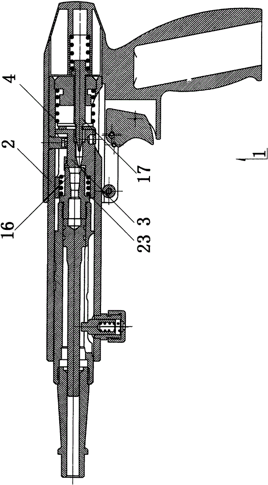
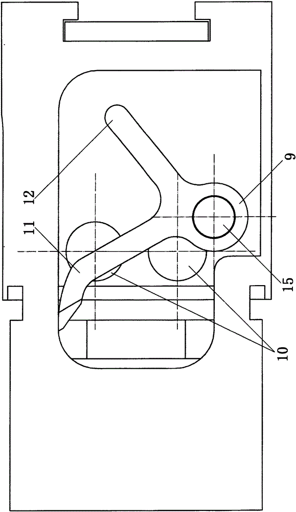
[0032] In the figure: 1 is the body, 2 is the shell, 3 is the firing pin seat, 4 is the return spring, 5 is the pop-up window, 6 is the hole, 7 is the pin, 8 is the mounting surface, 9 is the shift fork, 10 is the magnet, 11 is the front fork, 12 is the rear fork, 13 is the bevel, 14 is the gap, 15 is the bolt (also can be threaded pin or rivet), 16 is the chamber body, 17 is the firing pin, 18 is the belt, 19 is the dial Groove, 20 is bullet groove, and 21 is nail shooting bullet, and 22 is protrusion, and 23 is back-moving spring.

[0033] The firing pin seat 3 is a part that has always existed in the structure of the nail shooter. It is located between the chamber body 16 and the firing pin 17. It is used to guide the firing pin 17 so that the head of the firing pin 17 passes through the firing pin quickly. The hole inside the seat 3, and stretch out, accurately strikes the bottom shell of the nail-shooting projectile in the chamber body 16, reaches the purpose of explosion...


PUM


Abstract

The invention relates to an automatic langrage feeding device of a nail shooting device. The automatic langrage feeding device comprises a body. The body comprises a shell and a firing pin base, a reset spring is arranged between the firing pin base and the shell, and the body is provided with a popup window. The body is provided with a hole, and a pin is arranged in the hole. A langrage groove is formed in the firing pin base. The firing pin base is provided with a mounting base, and a shifting fork and the mounting face are in rotary connection. Magnets are arranged on the mounting face. A front fork and a rear fork are arranged on the shifting fork. An overall lifting margin exists between the front fork and the mounting face. The rear fork and the pin match to achieve linkage. The automatic langrage feeding device has the beneficial effects that an original firing pin base structure is improved, the shifting fork is driven by power to alternately rotate through reciprocating motion of the reset spring, and therefore a langrage band is stirred to move, the action synchronism of a langrage shifting mechanism and the nail shooting device is good, and continuous operation can be achieved without human intervention. In addition, parts to which the improvement relates are small in size and light and are all internally arranged, the peripheral size of the whole nail shooting device cannot be increased, and added weight can be neglected.

Description

technical field [0001] The invention discloses a nail shooting device. Background technique [0002] The nail shooter is a tool that uses a firing pin to fire a nail bomb, and the thrust generated by the explosion of gunpowder in the nail gun acts as a power to move the ejector rod and drive the nail into the building. [0003] The principle of the firing device of the existing nail shooter is: the firing pin strikes the bottom shell of the nail shooter through motion, so that the nail shooter explodes to generate thrust, pushes the nailer rod to hit the nail, injects the nail into the base, and completes the operation Task. [0004] Most of the nail bullets used by existing nail shooters use a single-shot loading method: that is, manually load a nail bullet, percussion, eject the shell, and load another round. Such a filling method has slow speed, low efficiency, long time and cumbersome filling actions. In order to overcome the above-mentioned shortcomings, in recent ye...

Claims


Application Information

Patent Timeline
IPC IPC(8): B25C1/00
Inventor 方福政
Owner YIBIN NANXI KECHENG ELECTROMECHANICAL FACTORY
Why Eureka
Eureka Blog
Learn More