Arm unit of spraying robot

A technology for spraying robots and arm parts, which is applied in the direction of claw arms, manipulators, spraying devices, etc., which can solve the problems of difficulty in ensuring the coaxiality of the transmission distance between the elbow joint and the wrist, affecting the accuracy of the spraying mechanism, and excessive load, etc., to eliminate errors , reduce the working intensity, and the effect of relative displacement compensation

A technology for spraying robots and arm parts, which is applied in the direction of claw arms, manipulators, spraying devices, etc., which can solve the problems of difficulty in ensuring the coaxiality of the transmission distance between the elbow joint and the wrist, affecting the accuracy of the spraying mechanism, and excessive load, etc., to eliminate errors , reduce the working intensity, and the effect of relative displacement compensation

CN105216009AInactive Publication Date: 2016-01-06CHONGQING CHANGJIANG COATING EQUIP

Image

  • Arm unit of spraying robot
  • Arm unit of spraying robot
  • Arm unit of spraying robot

Examples


Embodiment Construction

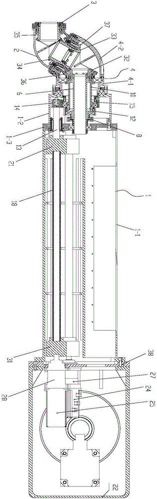
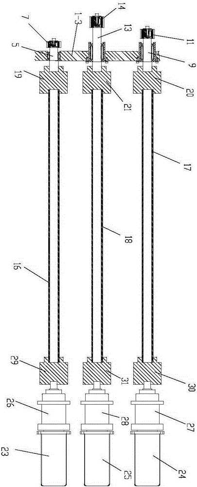
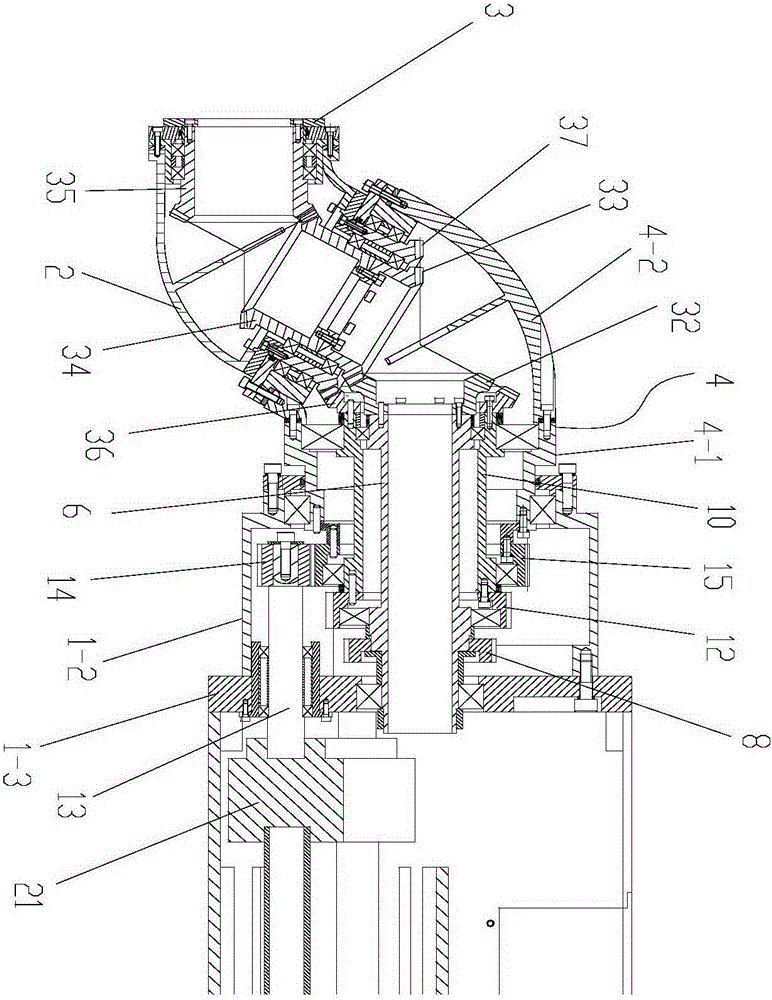
[0021] figure 1 It is a schematic diagram of the structure of the present invention. figure 2 It is a schematic diagram of the connection structure between the transmission shaft and the corresponding power input shaft in the present invention, image 3 It is an enlarged view of the wrist structure in the present invention, as shown in the figure: the spraying robot arm part of the present embodiment includes a support arm 1, a wrist 2 and a terminal arm 3 that is rotationally connected with the wrist 2, and is connected with the support arm 1 The connecting part 4, which rotates at the end and cooperates with the wrist 2, also includes a first driving mechanism for driving the terminal arm 3 to rotate, a second driving mechanism for driving the rotation of the wrist 2 and a second driving mechanism for driving the connecting part 4 to rotate. The third driving mechanism; wherein, the terminal arm 3 is used to install the final spraying mechanism, the wrist 2 is arc-shaped, ...


PUM


Abstract

The invention discloses an arm unit of a spraying robot. The arm unit comprises a supporting arm, a wrist, and a tail end arm in rotational connection with the wrist, as well as a connecting piece in rotational fit with a tail end of the supporting arm and the wrist; the arm unit further comprises a first driving mechanism for driving the tail end arm to rotate, a second driving mechanism for driving the wrist to rotate and a third driving mechanism for driving the connecting piece to rotate; each driving mechanism is provided with a power input assembly matched with a transmission shaft to input power, and then the power is further accurately input into a driving assembly for directly driving the unit to rotate through power transfer of the power input assembly; by means of stepping, errors caused by long-distance transmission coaxiality can be eliminated; meanwhile, in the operating process of the spraying robot, a relative displacement between the wrist and the elbow joint of the tail end mechanical arm is compensated to ensure the accuracy of spraying; meanwhile, a rotating speed and a torque can be changed to reduce the working strength.

Description

technical field [0001] The invention relates to the field of robot equipment, in particular to a spraying robot arm part. Background technique [0002] Spraying robot, also called painting robot, is a robot that can automatically spray paint or spray other coatings. A spraying robot generally includes a plurality of mechanical arms that are connected in sequence. A spraying mechanism (located on the wrist of the spraying robot) is installed on the mechanical arm at the end for spraying operations, and the spraying mechanism at the end has multiple degrees of freedom of movement. A driving mechanism for driving the spraying mechanism to move along multiple degrees of freedom is provided. Among them, the driving mechanism mainly includes a power part and a transmission part. In order to reduce the weight of the spraying mechanism as much as possible, the power part of the driving mechanism is usually placed at the elbow joint at the rear end of the mechanical arm, and through...

Claims


Application Information

Patent Timeline
06 Jan 2016
Publication
CN105216009A
IPC
B25J18/00; B05B13/04
Inventors
唐倩; 熊浩