Mechanical transfer arm and vacuum transfer cavity

A vacuum transfer and robotic arm technology, applied in the field of robotic arms, can solve the problems of limited elongation distance at the end of the structure, high production cost, and small room for transformation, and achieve the effect of increasing the scope of application, simple and effective structure, and simple cost

Active Publication Date: 2016-01-06
FERMION INSTR SHANGHAI CO LTD
View PDF8 Cites 0 Cited by
  • Summary
  • Abstract
  • Description
  • Claims
  • Application Information

AI Technical Summary

Problems solved by technology

[0003] The patent application number CN200420109354.1 discloses a gecko-type multi-stage sample feeder, but the structure is complex and the accuracy is poor, and it is not suitable for ultra-high vacuum systems
The patent application number CN201410395415.3 discloses a cutting device for tubular products, which involves a three-stage telescopic mechanism, which mainly realizes the shrinking function of the cutting knife through the rotation of the screw, and has the disadvantage of high cost and easy wear
[0004] In the prior art, when the transmission of the mechanical arm is realized in a cavity of a certain size, the elongation distance of the end of a part of the structure is limited, and the other part can be extended longer, but there are many transmission parts, the structure is complicated, the room for modification is small, and the production cost is high. Poor compatibility with different UHV systems

Method used


Image

  • Mechanical transfer arm and vacuum transfer cavity
  • Mechanical transfer arm and vacuum transfer cavity
  • Mechanical transfer arm and vacuum transfer cavity

Examples


Embodiment Construction

[0029] The following will clearly and completely describe the technical solutions in the embodiments of the present invention with reference to the accompanying drawings in the embodiments of the present invention. Obviously, the described embodiments are only some, not all, embodiments of the present invention. Based on the embodiments of the present invention, all other embodiments obtained by persons of ordinary skill in the art without making creative efforts belong to the protection scope of the present invention.

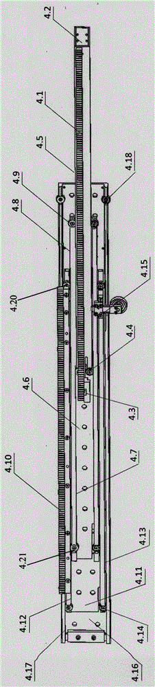
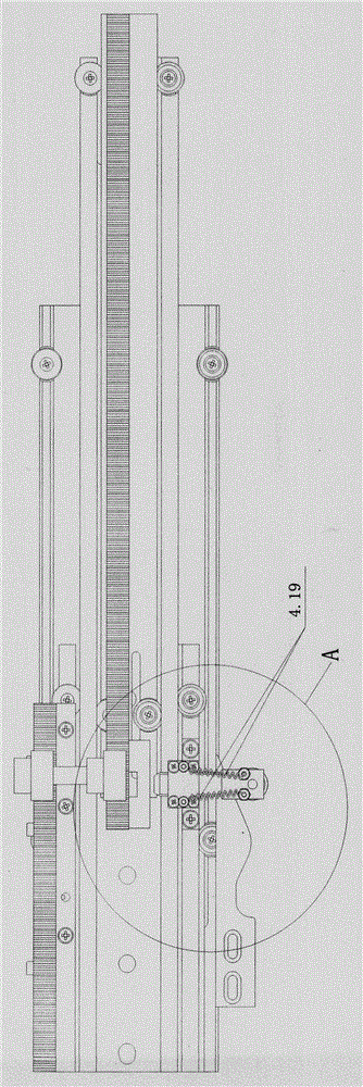
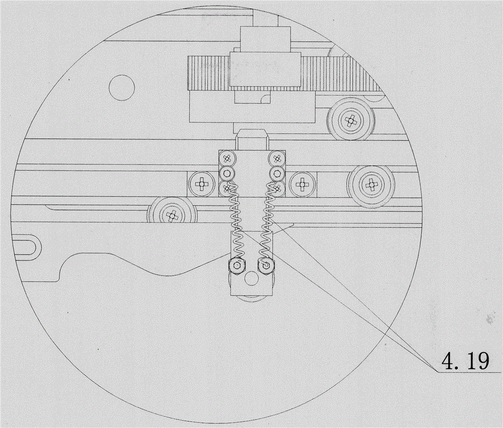
[0030] The mechanical transmission arm of the present invention includes three levels of driving devices: first level driving device, second level driving device and third level driving device, and may also include more levels of driving arms. below in Figure 1-Figure 3 In the structure of the preferred embodiment shown, the specific structure of the present invention will be described in detail by taking a four-stage mechanical transfer arm including a fourt...


PUM


Abstract

The invention provides a mechanical transfer arm which comprises a first-stage driving device, a second-stage driving device and a third-stage driving device. A fourth-stage driving device or more can be arranged as needed. The first-stage driving device is connected with the third-stage driving device through a plug pin mechanism capable of being automatically opened and closed, so that three grades of mechanical transfer arms which are nested extend out in sequence, and the maximum extension amount can reach more than 850 mm. The device is concise and effective in structure, and the design pays attention to the compatibility of different ultrahigh vacuum experiment systems, so that the cost is reduced, operation is simplified, and the application range is widened.

Description

technical field [0001] The invention relates to the mechanical field, in particular to a mechanical arm in an ultra-vacuum environment. Background technique [0002] Ultra-high vacuum means that the vacuum degree is better than 10 -6 In the artificial vacuum environment of Pa, according to the speed at which gas molecules reach the material surface and the gas mean free path and other parameters, we can calculate that the time for gas molecules to cover a monoatomic layer on the material surface under normal atmospheric pressure is 10 -9 s, while at 10 -10 In the Pa-level ultra-high vacuum environment, the time will be greatly extended to 10 4 s. It can be seen that in the field of scientific research, the degree of vacuum is very important to measure the intrinsic properties of the sample surface. At present, ultra-high vacuum experimental systems have been widely used in various fields such as semiconductors, physics, chemistry, materials and biological sciences, for g...

Claims


Application Information

Patent Timeline
Patent Type & Authority Applications(China)
IPC IPC(8): B25J18/02B25J9/10
Inventor 谢英英池彬赵嘉峰欧宏炜
Owner FERMION INSTR SHANGHAI CO LTD
Why Eureka
Try Eureka