Elevator traction machine

A technology for traction machines and elevators, which is applied in the field of traction machines for elevators, and can solve problems such as the complex structure of the whole machine, the complicated shape and structure of the sheave, and the increase in the volume and weight of the sheave, so as to keep the structure of the whole machine simple Simplification, layout and operation are convenient, and the effect of reducing production cost

Inactive Publication Date: 2016-01-06
SHANGHAI MITSUBISHI ELEVATOR CO LTD
View PDF5 Cites 8 Cited by
  • Summary
  • Abstract
  • Description
  • Claims
  • Application Information

AI Technical Summary

Problems solved by technology

[0005] First, the shape and structure of the sheave is complicated
The sheave needs to be equipped with a sheave shaft protruding to one side, and a bearing installation part needs to be provided on the sheave shaft; the sheave needs to be provided with a fixed installation part connected with the main body of the rotating part; these all make the shape and structure of the sheave more complicated, and the rope The volume weight of the wheel increases, and the production cost increases
[0006] Second, the structure of the traction machine is complex

Method used


Image

  • Elevator traction machine
  • Elevator traction machine
  • Elevator traction machine

Examples


Embodiment Construction

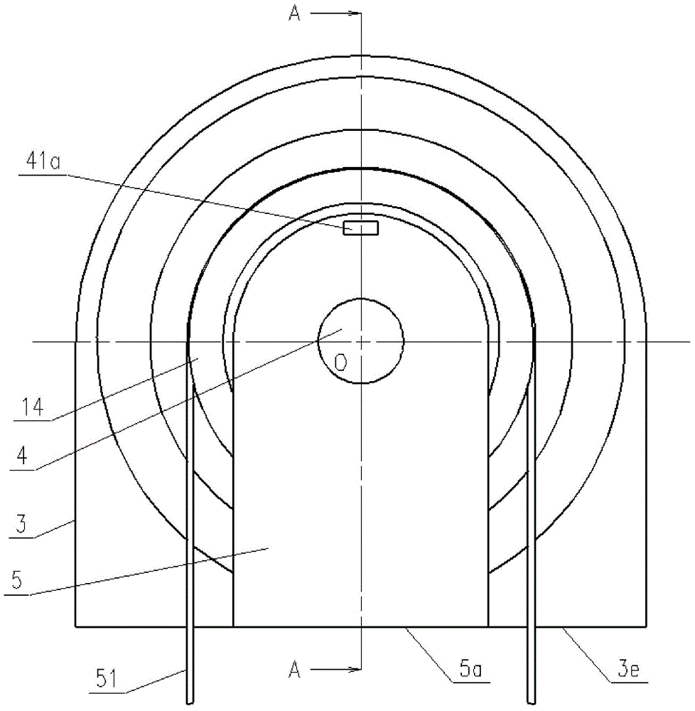
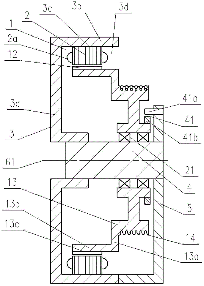
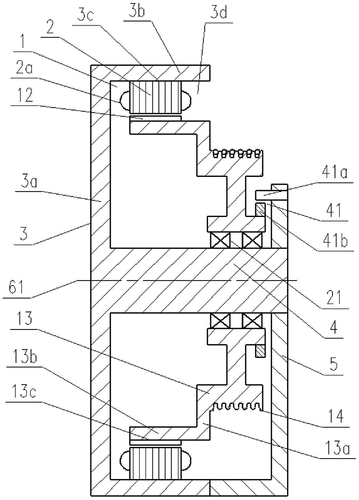
[0037] Such as figure 1 and figure 2 Shown is the first embodiment of the elevator traction machine of the present invention, comprising a motor 1, a fixed frame 3, a fixed main shaft 4, a rotor case 13, a sheave 14 for driving the elevator rope 51, a bearing 21, and a supporting frame 5;

[0038] The motor 1 comprises a stator 2 and a rotor 12 provided with a stator coil 2a, and the stator 2 and the rotor 12 are relatively arranged; the motor 1 is a cylindrical motor, which provides rotational power for the sheave 14 driving the elevator rope 51;

[0039] The fixed base 3 has a hollow disc-shaped extension 3a extending radially outward, a cylindrical portion 3b bent from the extension 3a to the vertical direction and extending axially, and a stator mounting portion 3c provided on the cylindrical portion 3b; The stator 2 is fixedly arranged at the stator installation part 3c;

[0040] The fixed main shaft 4 is arranged near the rotation center 61, and the fixed main shaft 4...


PUM


Abstract

The invention discloses an elevator traction machine which comprises an electromotor, a fixing machine base, a fixed mainshaft, a rotor case, a rope sheave, a bearing and a supporting machine base, wherein the rope sheave is used for driving an elevator rope; a stator mounting part is arranged at a cylinder part, axially extending, of the fixing machine base, and a rotor mounting part is arranged at a cylinder part, axially extending, of the rotor case; the rotor mounting part and the stator mounting part are opposite to each other; the rope sheave is fixedly connected with the rotor case, and the fixed mainshaft is used for supporting the rotation of the rotor case through the bearing; the supporting machine base and the fixing machine base are used for supporting the fixed mainshaft together, and an encoder is arranged between the rotor case and the supporting machine base. The elevator traction machine with the cylinder type electromotor is in a new double-supporting structure for the shaft, the structure and the bearing way of the traction machine are beneficial to improving the loading capacity of the traction machine, and the whole structure of the traction machine is simpler.

Description

technical field [0001] The invention relates to an elevator driving device, in particular to an elevator traction machine. Background technique [0002] An elevator with a large load capacity and a large lifting height also has a large load on the traction machine, which requires the traction machine to have a large load-carrying capacity. If the traction machine adopts a shaft cantilever support structure, sometimes the strength cannot be guaranteed. In order to ensure the strength, in the case of large load and large lifting height, the elevator traction machine adopts the double support structure of the shaft. [0003] Chinese invention patent ZL200480002089.X discloses a traction machine for elevators, which is a traditional traction machine for elevators with a double-supported shaft structure. The structural features of the traction machine are: using a cylindrical motor; adopting a complete machine structure with two ends supporting the middle load; the base is provi...

Claims


Application Information

Patent Timeline
Patent Type & Authority Applications(China)
IPC IPC(8): B66B11/04
Inventor 方凯李伟
Owner SHANGHAI MITSUBISHI ELEVATOR CO LTD
Why Eureka
Try Eureka