Liquid material filling control device and method

A liquid material and control device technology, applied in liquid bottling, liquid processing, packaging, etc., can solve the problems of irregular fluctuation of the flow of the filling head, difficult to clean, and low filling speed, and simplify the filling process. , Reduce material waste, improve speed and accuracy

Active Publication Date: 2016-01-06
BEIJING AREOSTANARD NEW TECH +2
View PDF6 Cites 8 Cited by
  • Summary
  • Abstract
  • Description
  • Claims
  • Application Information

AI Technical Summary

Problems solved by technology

The so-called pressure filling, the pipeline is directly connected to the filling head, and the material is directly transported to the filling head through the feeding pump, so the filling under pressure can ensure a fast filling speed, but due to the fluctuation of the feeding pressure, especially For equipment with multiple filling heads, when a filling head is closed, it will cause pressure fluctuations in the pipeline, resulting in irregular fluctuations in the flow of other filling heads, which seriously affects the filling accuracy of the equipment
The so-called self-flow filling, the material is first conveyed into the material box through the pipeline, and then the material box is connected to the filling head through the pipeline. The filling pressure mainly depends on the density of the material and the height of the material liquid level in the material box during filling. For many For equipment with a filling head, when the filling head is closed, the pressure fluctuations generated will be fed back into the material box. Since the volume of the material box is large enough, the material level fluctuations caused by pressure fluctuations are small and negligible, so The material box acts as a suction container for pressure fluctuations, ensuring the basic stability of material pressure and flow. Therefore, self-flow filling solves the disadvantage of poor control of filling accuracy due to pressure fluctuations in pressure filling, but the filling of self-flow filling The speed is low, and the material box used is generally large in size, which is not easy to clean and easily causes material pollution

Method used


Image

  • Liquid material filling control device and method
  • Liquid material filling control device and method

Examples


Embodiment Construction

[0017] The present invention will be further described below in conjunction with the accompanying drawings and embodiments.

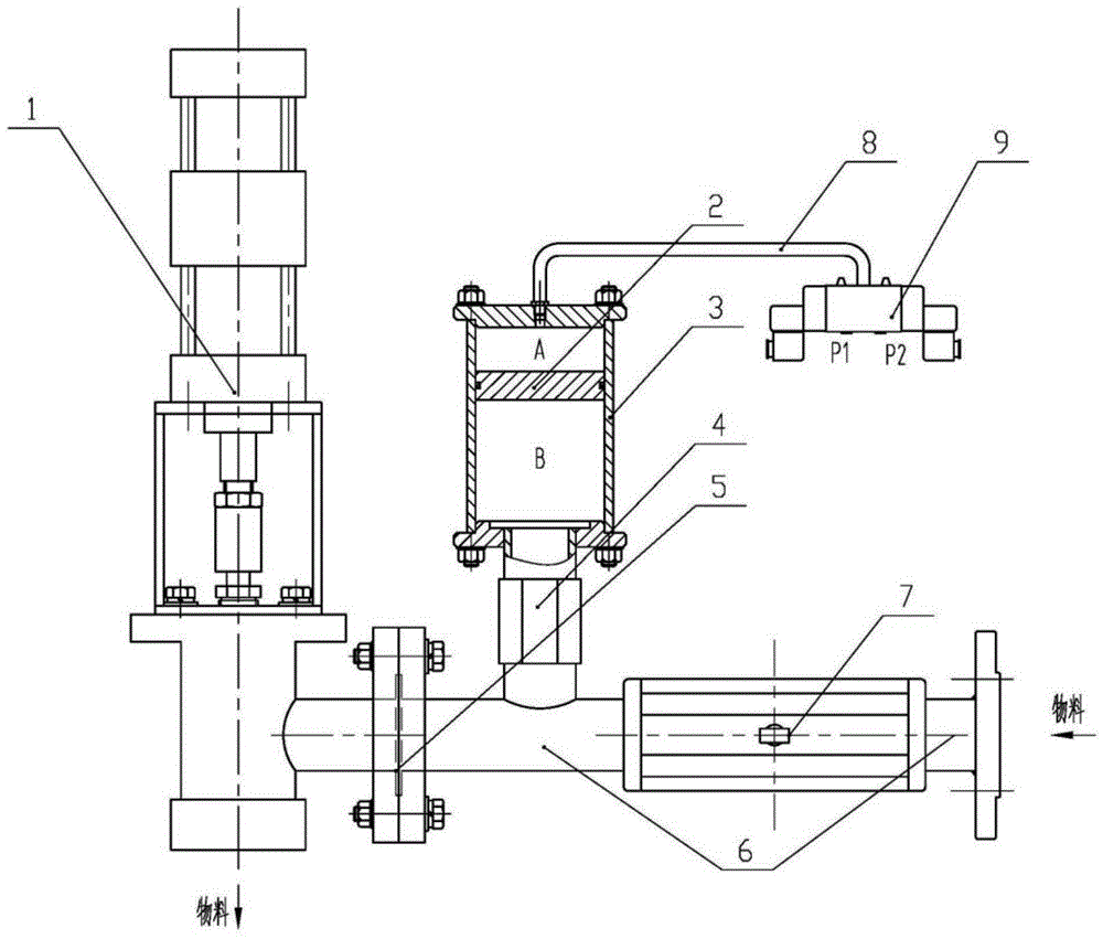
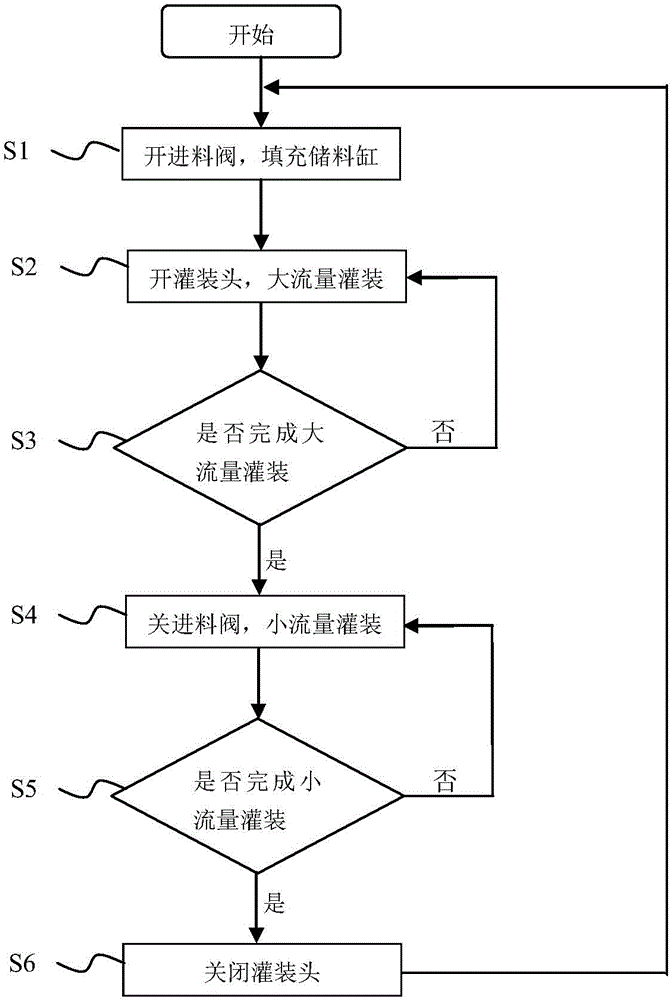
[0018] At present, liquid quantitative filling equipment, in order to meet the dual requirements of filling speed and filling accuracy, mostly adopts the double-speed filling mode: firstly, high-speed filling with large flow rate is used, and the large flow rate is turned off when the filling volume reaches the required filling volume. Filling, switch to small flow filling to meet the requirements of high speed and high precision. Therefore, the idea of ​​the present invention is: in combination with the characteristics of the above method, when the filling equipment is filling at a large flow rate, it uses pressure filling to increase the filling speed, and when filling at a small flow rate, it is converted to self-flow filling or Stable pressure filling similar to gravity filling to ensure filling accuracy.

[0019] Such as figure 1 As shown, the li...


PUM


Abstract

The invention relates to a liquid material filling control device and method. The device comprises a filling head (1), a material inlet pipe (6) and a material storage cylinder (3); a material inlet valve (7) is installed in the middle of the material inlet pipe (6); one end of the material inlet pipe (6) is connected with the filling head (1); to-be-filled materials are fed through the other end of the material inlet pipe (6); the material inlet valve (7) controls the materials to flow or stop in the material inlet pipe (6); a branch is designed between a flange (5) and the material inlet valve (7) and on the material inlet pipe (6) and connected with the material storage cylinder (3) through a threaded pipe (4); the material storage cylinder (3) comprises an air cavity (A) and a material cavity (B) which are sealed and isolated through pistons (2); the air cavity (A) is connected with a control valve (9) through an air pipe (8); the material cavity (B) is communicated with the material inlet pipe (6); the control valve (9) guides in or cuts off industrial instrument air or atmosphere. By means of the liquid material filling control device and method, speed and accuracy of the filling process are improved, the filling process is simplified, and material waste is reduced.

Description

technical field [0001] The invention relates to a liquid filling equipment suitable for the fields of medicine, food, chemical industry and the like, in particular to a liquid material filling control device which can realize alternate liquid filling under pressure and self-flowing filling. Background technique [0002] At present, the liquid quantitative filling equipment in the field of filling and packaging generally adopts two filling methods: pressure filling and gravity filling. The so-called pressure filling, the pipeline is directly connected to the filling head, and the material is directly transported to the filling head through the feeding pump, so the filling under pressure can ensure a fast filling speed, but due to the fluctuation of the feeding pressure, especially For equipment with multiple filling heads, when a certain filling head is closed, the pressure of the pipeline will fluctuate, resulting in irregular fluctuations in the flow of other filling heads,...

Claims


Application Information

Patent Timeline
Patent Type & Authority Applications(China)
IPC IPC(8): B67C3/28
Inventor 李红果叶岷崔岩石卓栋化北
Owner BEIJING AREOSTANARD NEW TECH
Why Eureka
Try Eureka